Notations
The Norwegian Subsea MRU outputs values (position and velocity) for all 6 degrees of freedom (DOFs):
-
The 3 translational DOFs are surge, sway and heave.
-
The 3 rotational DOFs are roll, pitch and yaw.
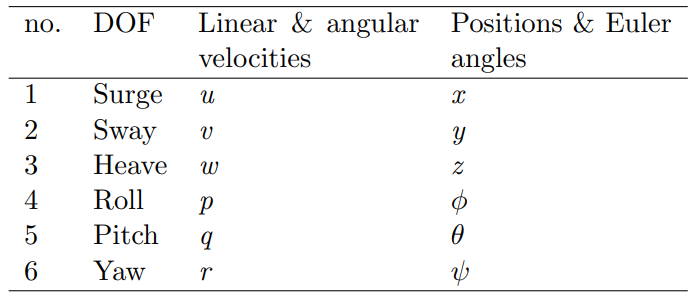
Organized into vectors, these are
%22%20aria-hidden%3D%22true%22%3E%0A%20%3Cuse%20xlink%3Ahref%3D%22%23E1-MJMAINB-70%22%20x%3D%220%22%20y%3D%220%22%3E%3C%2Fuse%3E%0A%20%3Cuse%20xlink%3Ahref%3D%22%23E1-MJMAIN-3D%22%20x%3D%22917%22%20y%3D%220%22%3E%3C%2Fuse%3E%0A%3Cg%20transform%3D%22translate(1973%2C0)%22%3E%0A%3Cg%20transform%3D%22translate(0%2C2153)%22%3E%0A%20%3Cuse%20xlink%3Ahref%3D%22%23E1-MJSZ4-23A1%22%20x%3D%220%22%20y%3D%22-1155%22%3E%3C%2Fuse%3E%0A%3Cg%20transform%3D%22translate(0%2C-2054.4966887417218)%20scale(1%2C0.5033112582781457)%22%3E%0A%20%3Cuse%20xlink%3Ahref%3D%22%23E1-MJSZ4-23A2%22%3E%3C%2Fuse%3E%0A%3C%2Fg%3E%0A%20%3Cuse%20xlink%3Ahref%3D%22%23E1-MJSZ4-23A3%22%20x%3D%220%22%20y%3D%22-3161%22%3E%3C%2Fuse%3E%0A%3C%2Fg%3E%0A%3Cg%20transform%3D%22translate(834%2C0)%22%3E%0A%3Cg%20transform%3D%22translate(-11%2C0)%22%3E%0A%20%3Cuse%20xlink%3Ahref%3D%22%23E1-MJMATHI-78%22%20x%3D%220%22%20y%3D%221353%22%3E%3C%2Fuse%3E%0A%20%3Cuse%20xlink%3Ahref%3D%22%23E1-MJMATHI-79%22%20x%3D%2237%22%20y%3D%22-47%22%3E%3C%2Fuse%3E%0A%20%3Cuse%20xlink%3Ahref%3D%22%23E1-MJMATHI-7A%22%20x%3D%2252%22%20y%3D%22-1453%22%3E%3C%2Fuse%3E%0A%3C%2Fg%3E%0A%3C%2Fg%3E%0A%3Cg%20transform%3D%22translate(1563%2C2153)%22%3E%0A%20%3Cuse%20xlink%3Ahref%3D%22%23E1-MJSZ4-23A4%22%20x%3D%220%22%20y%3D%22-1155%22%3E%3C%2Fuse%3E%0A%3Cg%20transform%3D%22translate(0%2C-2054.4966887417218)%20scale(1%2C0.5033112582781457)%22%3E%0A%20%3Cuse%20xlink%3Ahref%3D%22%23E1-MJSZ4-23A5%22%3E%3C%2Fuse%3E%0A%3C%2Fg%3E%0A%20%3Cuse%20xlink%3Ahref%3D%22%23E1-MJSZ4-23A6%22%20x%3D%220%22%20y%3D%22-3161%22%3E%3C%2Fuse%3E%0A%3C%2Fg%3E%0A%3C%2Fg%3E%0A%20%3Cuse%20xlink%3Ahref%3D%22%23E1-MJMAIN-2C%22%20x%3D%224371%22%20y%3D%220%22%3E%3C%2Fuse%3E%0A%20%3Cuse%20xlink%3Ahref%3D%22%23E1-MJMAINB-76%22%20x%3D%225816%22%20y%3D%220%22%3E%3C%2Fuse%3E%0A%20%3Cuse%20xlink%3Ahref%3D%22%23E1-MJMAIN-3D%22%20x%3D%226701%22%20y%3D%220%22%3E%3C%2Fuse%3E%0A%3Cg%20transform%3D%22translate(7757%2C0)%22%3E%0A%3Cg%20transform%3D%22translate(0%2C2150)%22%3E%0A%20%3Cuse%20xlink%3Ahref%3D%22%23E1-MJSZ4-23A1%22%20x%3D%220%22%20y%3D%22-1155%22%3E%3C%2Fuse%3E%0A%3Cg%20transform%3D%22translate(0%2C-2048.5066225165565)%20scale(1%2C0.49337748344370863)%22%3E%0A%20%3Cuse%20xlink%3Ahref%3D%22%23E1-MJSZ4-23A2%22%3E%3C%2Fuse%3E%0A%3C%2Fg%3E%0A%20%3Cuse%20xlink%3Ahref%3D%22%23E1-MJSZ4-23A3%22%20x%3D%220%22%20y%3D%22-3155%22%3E%3C%2Fuse%3E%0A%3C%2Fg%3E%0A%3Cg%20transform%3D%22translate(834%2C0)%22%3E%0A%3Cg%20transform%3D%22translate(-11%2C0)%22%3E%0A%20%3Cuse%20xlink%3Ahref%3D%22%23E1-MJMATHI-75%22%20x%3D%2272%22%20y%3D%221350%22%3E%3C%2Fuse%3E%0A%20%3Cuse%20xlink%3Ahref%3D%22%23E1-MJMATHI-76%22%20x%3D%22115%22%20y%3D%22-50%22%3E%3C%2Fuse%3E%0A%20%3Cuse%20xlink%3Ahref%3D%22%23E1-MJMATHI-77%22%20x%3D%220%22%20y%3D%22-1450%22%3E%3C%2Fuse%3E%0A%3C%2Fg%3E%0A%3C%2Fg%3E%0A%3Cg%20transform%3D%22translate(1707%2C2150)%22%3E%0A%20%3Cuse%20xlink%3Ahref%3D%22%23E1-MJSZ4-23A4%22%20x%3D%220%22%20y%3D%22-1155%22%3E%3C%2Fuse%3E%0A%3Cg%20transform%3D%22translate(0%2C-2048.5066225165565)%20scale(1%2C0.49337748344370863)%22%3E%0A%20%3Cuse%20xlink%3Ahref%3D%22%23E1-MJSZ4-23A5%22%3E%3C%2Fuse%3E%0A%3C%2Fg%3E%0A%20%3Cuse%20xlink%3Ahref%3D%22%23E1-MJSZ4-23A6%22%20x%3D%220%22%20y%3D%22-3155%22%3E%3C%2Fuse%3E%0A%3C%2Fg%3E%0A%3C%2Fg%3E%0A%20%3Cuse%20xlink%3Ahref%3D%22%23E1-MJMAIN-2C%22%20x%3D%2210299%22%20y%3D%220%22%3E%3C%2Fuse%3E%0A%20%3Cuse%20xlink%3Ahref%3D%22%23E1-MJMAINB-398%22%20x%3D%2211744%22%20y%3D%220%22%3E%3C%2Fuse%3E%0A%20%3Cuse%20xlink%3Ahref%3D%22%23E1-MJMAIN-3D%22%20x%3D%2212917%22%20y%3D%220%22%3E%3C%2Fuse%3E%0A%3Cg%20transform%3D%22translate(13973%2C0)%22%3E%0A%3Cg%20transform%3D%22translate(0%2C2156)%22%3E%0A%20%3Cuse%20xlink%3Ahref%3D%22%23E1-MJSZ4-23A1%22%20x%3D%220%22%20y%3D%22-1155%22%3E%3C%2Fuse%3E%0A%3Cg%20transform%3D%22translate(0%2C-2060.4867549668875)%20scale(1%2C0.5132450331125827)%22%3E%0A%20%3Cuse%20xlink%3Ahref%3D%22%23E1-MJSZ4-23A2%22%3E%3C%2Fuse%3E%0A%3C%2Fg%3E%0A%20%3Cuse%20xlink%3Ahref%3D%22%23E1-MJSZ4-23A3%22%20x%3D%220%22%20y%3D%22-3167%22%3E%3C%2Fuse%3E%0A%3C%2Fg%3E%0A%3Cg%20transform%3D%22translate(834%2C0)%22%3E%0A%3Cg%20transform%3D%22translate(-11%2C0)%22%3E%0A%20%3Cuse%20xlink%3Ahref%3D%22%23E1-MJMATHI-3D5%22%20x%3D%2227%22%20y%3D%221356%22%3E%3C%2Fuse%3E%0A%20%3Cuse%20xlink%3Ahref%3D%22%23E1-MJMATHI-3B8%22%20x%3D%2291%22%20y%3D%22-50%22%3E%3C%2Fuse%3E%0A%20%3Cuse%20xlink%3Ahref%3D%22%23E1-MJMATHI-3C8%22%20x%3D%220%22%20y%3D%22-1450%22%3E%3C%2Fuse%3E%0A%3C%2Fg%3E%0A%3C%2Fg%3E%0A%3Cg%20transform%3D%22translate(1642%2C2156)%22%3E%0A%20%3Cuse%20xlink%3Ahref%3D%22%23E1-MJSZ4-23A4%22%20x%3D%220%22%20y%3D%22-1155%22%3E%3C%2Fuse%3E%0A%3Cg%20transform%3D%22translate(0%2C-2060.4867549668875)%20scale(1%2C0.5132450331125827)%22%3E%0A%20%3Cuse%20xlink%3Ahref%3D%22%23E1-MJSZ4-23A5%22%3E%3C%2Fuse%3E%0A%3C%2Fg%3E%0A%20%3Cuse%20xlink%3Ahref%3D%22%23E1-MJSZ4-23A6%22%20x%3D%220%22%20y%3D%22-3167%22%3E%3C%2Fuse%3E%0A%3C%2Fg%3E%0A%3C%2Fg%3E%0A%20%3Cuse%20xlink%3Ahref%3D%22%23E1-MJMAIN-2C%22%20x%3D%2216450%22%20y%3D%220%22%3E%3C%2Fuse%3E%0A%20%3Cuse%20xlink%3Ahref%3D%22%23E1-MJMATHI-3C9%22%20x%3D%2217895%22%20y%3D%220%22%3E%3C%2Fuse%3E%0A%20%3Cuse%20xlink%3Ahref%3D%22%23E1-MJMAIN-3D%22%20x%3D%2218795%22%20y%3D%220%22%3E%3C%2Fuse%3E%0A%3Cg%20transform%3D%22translate(19851%2C0)%22%3E%0A%3Cg%20transform%3D%22translate(0%2C2150)%22%3E%0A%20%3Cuse%20xlink%3Ahref%3D%22%23E1-MJSZ4-23A1%22%20x%3D%220%22%20y%3D%22-1155%22%3E%3C%2Fuse%3E%0A%3Cg%20transform%3D%22translate(0%2C-2048.5066225165565)%20scale(1%2C0.49337748344370863)%22%3E%0A%20%3Cuse%20xlink%3Ahref%3D%22%23E1-MJSZ4-23A2%22%3E%3C%2Fuse%3E%0A%3C%2Fg%3E%0A%20%3Cuse%20xlink%3Ahref%3D%22%23E1-MJSZ4-23A3%22%20x%3D%220%22%20y%3D%22-3155%22%3E%3C%2Fuse%3E%0A%3C%2Fg%3E%0A%3Cg%20transform%3D%22translate(834%2C0)%22%3E%0A%3Cg%20transform%3D%22translate(-11%2C0)%22%3E%0A%20%3Cuse%20xlink%3Ahref%3D%22%23E1-MJMATHI-70%22%20x%3D%220%22%20y%3D%221350%22%3E%3C%2Fuse%3E%0A%20%3Cuse%20xlink%3Ahref%3D%22%23E1-MJMATHI-71%22%20x%3D%2221%22%20y%3D%22-50%22%3E%3C%2Fuse%3E%0A%20%3Cuse%20xlink%3Ahref%3D%22%23E1-MJMATHI-72%22%20x%3D%2226%22%20y%3D%22-1450%22%3E%3C%2Fuse%3E%0A%3C%2Fg%3E%0A%3C%2Fg%3E%0A%3Cg%20transform%3D%22translate(1494%2C2150)%22%3E%0A%20%3Cuse%20xlink%3Ahref%3D%22%23E1-MJSZ4-23A4%22%20x%3D%220%22%20y%3D%22-1155%22%3E%3C%2Fuse%3E%0A%3Cg%20transform%3D%22translate(0%2C-2048.5066225165565)%20scale(1%2C0.49337748344370863)%22%3E%0A%20%3Cuse%20xlink%3Ahref%3D%22%23E1-MJSZ4-23A5%22%3E%3C%2Fuse%3E%0A%3C%2Fg%3E%0A%20%3Cuse%20xlink%3Ahref%3D%22%23E1-MJSZ4-23A6%22%20x%3D%220%22%20y%3D%22-3155%22%3E%3C%2Fuse%3E%0A%3C%2Fg%3E%0A%3C%2Fg%3E%0A%20%3Cuse%20xlink%3Ahref%3D%22%23E1-MJMAIN-2C%22%20x%3D%2222180%22%20y%3D%220%22%3E%3C%2Fuse%3E%0A%3C%2Fg%3E%0A%3C%2Fsvg%3E)
where %22%20aria-hidden%3D%22true%22%3E%0A%20%3Cuse%20xlink%3Ahref%3D%22%23E1-MJMAINB-70%22%20x%3D%220%22%20y%3D%220%22%3E%3C%2Fuse%3E%0A%20%3Cuse%20xlink%3Ahref%3D%22%23E1-MJMAIN-2208%22%20x%3D%22917%22%20y%3D%220%22%3E%3C%2Fuse%3E%0A%3Cg%20transform%3D%22translate(1862%2C0)%22%3E%0A%20%3Cuse%20xlink%3Ahref%3D%22%23E1-MJAMS-52%22%20x%3D%220%22%20y%3D%220%22%3E%3C%2Fuse%3E%0A%3Cg%20transform%3D%22translate(722%2C412)%22%3E%0A%20%3Cuse%20transform%3D%22scale(0.707)%22%20xlink%3Ahref%3D%22%23E1-MJMAIN-33%22%20x%3D%220%22%20y%3D%220%22%3E%3C%2Fuse%3E%0A%20%3Cuse%20transform%3D%22scale(0.707)%22%20xlink%3Ahref%3D%22%23E1-MJMAIN-D7%22%20x%3D%22500%22%20y%3D%220%22%3E%3C%2Fuse%3E%0A%20%3Cuse%20transform%3D%22scale(0.707)%22%20xlink%3Ahref%3D%22%23E1-MJMAIN-31%22%20x%3D%221279%22%20y%3D%220%22%3E%3C%2Fuse%3E%0A%3C%2Fg%3E%0A%3C%2Fg%3E%0A%3C%2Fg%3E%0A%3C%2Fsvg%3E)
%22%20aria-hidden%3D%22true%22%3E%0A%20%3Cuse%20xlink%3Ahref%3D%22%23E1-MJMAINB-76%22%20x%3D%220%22%20y%3D%220%22%3E%3C%2Fuse%3E%0A%20%3Cuse%20xlink%3Ahref%3D%22%23E1-MJMAIN-2208%22%20x%3D%22885%22%20y%3D%220%22%3E%3C%2Fuse%3E%0A%3Cg%20transform%3D%22translate(1830%2C0)%22%3E%0A%20%3Cuse%20xlink%3Ahref%3D%22%23E1-MJAMS-52%22%20x%3D%220%22%20y%3D%220%22%3E%3C%2Fuse%3E%0A%3Cg%20transform%3D%22translate(722%2C412)%22%3E%0A%20%3Cuse%20transform%3D%22scale(0.707)%22%20xlink%3Ahref%3D%22%23E1-MJMAIN-33%22%20x%3D%220%22%20y%3D%220%22%3E%3C%2Fuse%3E%0A%20%3Cuse%20transform%3D%22scale(0.707)%22%20xlink%3Ahref%3D%22%23E1-MJMAIN-D7%22%20x%3D%22500%22%20y%3D%220%22%3E%3C%2Fuse%3E%0A%20%3Cuse%20transform%3D%22scale(0.707)%22%20xlink%3Ahref%3D%22%23E1-MJMAIN-31%22%20x%3D%221279%22%20y%3D%220%22%3E%3C%2Fuse%3E%0A%3C%2Fg%3E%0A%3C%2Fg%3E%0A%3C%2Fg%3E%0A%3C%2Fsvg%3E)
%22%20aria-hidden%3D%22true%22%3E%0A%20%3Cuse%20xlink%3Ahref%3D%22%23E1-MJMAIN-398%22%20x%3D%220%22%20y%3D%220%22%3E%3C%2Fuse%3E%0A%20%3Cuse%20xlink%3Ahref%3D%22%23E1-MJMAIN-2208%22%20x%3D%221056%22%20y%3D%220%22%3E%3C%2Fuse%3E%0A%3Cg%20transform%3D%22translate(2001%2C0)%22%3E%0A%20%3Cuse%20xlink%3Ahref%3D%22%23E1-MJAMS-52%22%20x%3D%220%22%20y%3D%220%22%3E%3C%2Fuse%3E%0A%3Cg%20transform%3D%22translate(722%2C412)%22%3E%0A%20%3Cuse%20transform%3D%22scale(0.707)%22%20xlink%3Ahref%3D%22%23E1-MJMAIN-33%22%20x%3D%220%22%20y%3D%220%22%3E%3C%2Fuse%3E%0A%20%3Cuse%20transform%3D%22scale(0.707)%22%20xlink%3Ahref%3D%22%23E1-MJMAIN-D7%22%20x%3D%22500%22%20y%3D%220%22%3E%3C%2Fuse%3E%0A%20%3Cuse%20transform%3D%22scale(0.707)%22%20xlink%3Ahref%3D%22%23E1-MJMAIN-31%22%20x%3D%221279%22%20y%3D%220%22%3E%3C%2Fuse%3E%0A%3C%2Fg%3E%0A%3C%2Fg%3E%0A%3C%2Fg%3E%0A%3C%2Fsvg%3E)
%22%20aria-hidden%3D%22true%22%3E%0A%20%3Cuse%20xlink%3Ahref%3D%22%23E1-MJMATHBI-3C9%22%20x%3D%220%22%20y%3D%220%22%3E%3C%2Fuse%3E%0A%20%3Cuse%20xlink%3Ahref%3D%22%23E1-MJMAIN-2208%22%20x%3D%22996%22%20y%3D%220%22%3E%3C%2Fuse%3E%0A%3Cg%20transform%3D%22translate(1941%2C0)%22%3E%0A%20%3Cuse%20xlink%3Ahref%3D%22%23E1-MJAMS-52%22%20x%3D%220%22%20y%3D%220%22%3E%3C%2Fuse%3E%0A%3Cg%20transform%3D%22translate(722%2C412)%22%3E%0A%20%3Cuse%20transform%3D%22scale(0.707)%22%20xlink%3Ahref%3D%22%23E1-MJMAIN-33%22%20x%3D%220%22%20y%3D%220%22%3E%3C%2Fuse%3E%0A%20%3Cuse%20transform%3D%22scale(0.707)%22%20xlink%3Ahref%3D%22%23E1-MJMAIN-D7%22%20x%3D%22500%22%20y%3D%220%22%3E%3C%2Fuse%3E%0A%20%3Cuse%20transform%3D%22scale(0.707)%22%20xlink%3Ahref%3D%22%23E1-MJMAIN-31%22%20x%3D%221279%22%20y%3D%220%22%3E%3C%2Fuse%3E%0A%3C%2Fg%3E%0A%3C%2Fg%3E%0A%3C%2Fg%3E%0A%3C%2Fsvg%3E)
Reference frames
The motion measured by the MRU can be represented in different reference frames. The 3 most important frames are:
-
NED, {
%22%20aria-hidden%3D%22true%22%3E%0A%20%3Cuse%20xlink%3Ahref%3D%22%23E1-MJMATHI-6E%22%20x%3D%220%22%20y%3D%220%22%3E%3C%2Fuse%3E%0A%3C%2Fg%3E%0A%3C%2Fsvg%3E)
%22%20aria-hidden%3D%22true%22%3E%0A%20%3Cuse%20xlink%3Ahref%3D%22%23E1-MJMAIN-3D%22%20x%3D%220%22%20y%3D%220%22%3E%3C%2Fuse%3E%0A%20%3Cuse%20xlink%3Ahref%3D%22%23E1-MJMAIN-5B%22%20x%3D%221056%22%20y%3D%220%22%3E%3C%2Fuse%3E%0A%3Cg%20transform%3D%22translate(1334%2C0)%22%3E%0A%20%3Cuse%20xlink%3Ahref%3D%22%23E1-MJMATHI-78%22%20x%3D%220%22%20y%3D%220%22%3E%3C%2Fuse%3E%0A%20%3Cuse%20transform%3D%22scale(0.707)%22%20xlink%3Ahref%3D%22%23E1-MJMATHI-6E%22%20x%3D%22809%22%20y%3D%22583%22%3E%3C%2Fuse%3E%0A%3C%2Fg%3E%0A%20%3Cuse%20xlink%3Ahref%3D%22%23E1-MJMAIN-2C%22%20x%3D%222431%22%20y%3D%220%22%3E%3C%2Fuse%3E%0A%3Cg%20transform%3D%22translate(2877%2C0)%22%3E%0A%20%3Cuse%20xlink%3Ahref%3D%22%23E1-MJMATHI-79%22%20x%3D%220%22%20y%3D%220%22%3E%3C%2Fuse%3E%0A%20%3Cuse%20transform%3D%22scale(0.707)%22%20xlink%3Ahref%3D%22%23E1-MJMATHI-6E%22%20x%3D%22706%22%20y%3D%22583%22%3E%3C%2Fuse%3E%0A%3C%2Fg%3E%0A%20%3Cuse%20xlink%3Ahref%3D%22%23E1-MJMAIN-2C%22%20x%3D%223901%22%20y%3D%220%22%3E%3C%2Fuse%3E%0A%3Cg%20transform%3D%22translate(4346%2C0)%22%3E%0A%20%3Cuse%20xlink%3Ahref%3D%22%23E1-MJMATHI-7A%22%20x%3D%220%22%20y%3D%220%22%3E%3C%2Fuse%3E%0A%20%3Cuse%20transform%3D%22scale(0.707)%22%20xlink%3Ahref%3D%22%23E1-MJMATHI-6E%22%20x%3D%22663%22%20y%3D%22583%22%3E%3C%2Fuse%3E%0A%3C%2Fg%3E%0A%20%3Cuse%20xlink%3Ahref%3D%22%23E1-MJMAIN-5D%22%20x%3D%225340%22%20y%3D%220%22%3E%3C%2Fuse%3E%0A%3C%2Fg%3E%0A%3C%2Fsvg%3E)
-
BODY, {
%22%20aria-hidden%3D%22true%22%3E%0A%20%3Cuse%20xlink%3Ahref%3D%22%23E1-MJMATHI-62%22%20x%3D%220%22%20y%3D%220%22%3E%3C%2Fuse%3E%0A%3C%2Fg%3E%0A%3C%2Fsvg%3E)
%22%20aria-hidden%3D%22true%22%3E%0A%20%3Cuse%20xlink%3Ahref%3D%22%23E1-MJMAIN-3D%22%20x%3D%220%22%20y%3D%220%22%3E%3C%2Fuse%3E%0A%20%3Cuse%20xlink%3Ahref%3D%22%23E1-MJMAIN-5B%22%20x%3D%221056%22%20y%3D%220%22%3E%3C%2Fuse%3E%0A%3Cg%20transform%3D%22translate(1334%2C0)%22%3E%0A%20%3Cuse%20xlink%3Ahref%3D%22%23E1-MJMATHI-78%22%20x%3D%220%22%20y%3D%220%22%3E%3C%2Fuse%3E%0A%20%3Cuse%20transform%3D%22scale(0.707)%22%20xlink%3Ahref%3D%22%23E1-MJMATHI-62%22%20x%3D%22809%22%20y%3D%22583%22%3E%3C%2Fuse%3E%0A%3C%2Fg%3E%0A%20%3Cuse%20xlink%3Ahref%3D%22%23E1-MJMAIN-2C%22%20x%3D%222310%22%20y%3D%220%22%3E%3C%2Fuse%3E%0A%3Cg%20transform%3D%22translate(2756%2C0)%22%3E%0A%20%3Cuse%20xlink%3Ahref%3D%22%23E1-MJMATHI-79%22%20x%3D%220%22%20y%3D%220%22%3E%3C%2Fuse%3E%0A%20%3Cuse%20transform%3D%22scale(0.707)%22%20xlink%3Ahref%3D%22%23E1-MJMATHI-62%22%20x%3D%22706%22%20y%3D%22583%22%3E%3C%2Fuse%3E%0A%3C%2Fg%3E%0A%20%3Cuse%20xlink%3Ahref%3D%22%23E1-MJMAIN-2C%22%20x%3D%223659%22%20y%3D%220%22%3E%3C%2Fuse%3E%0A%3Cg%20transform%3D%22translate(4104%2C0)%22%3E%0A%20%3Cuse%20xlink%3Ahref%3D%22%23E1-MJMATHI-7A%22%20x%3D%220%22%20y%3D%220%22%3E%3C%2Fuse%3E%0A%20%3Cuse%20transform%3D%22scale(0.707)%22%20xlink%3Ahref%3D%22%23E1-MJMATHI-62%22%20x%3D%22663%22%20y%3D%22583%22%3E%3C%2Fuse%3E%0A%3C%2Fg%3E%0A%20%3Cuse%20xlink%3Ahref%3D%22%23E1-MJMAIN-5D%22%20x%3D%224977%22%20y%3D%220%22%3E%3C%2Fuse%3E%0A%3C%2Fg%3E%0A%3C%2Fsvg%3E)
-
MRU, {
%22%20aria-hidden%3D%22true%22%3E%0A%20%3Cuse%20xlink%3Ahref%3D%22%23E1-MJMATHI-6D%22%20x%3D%220%22%20y%3D%220%22%3E%3C%2Fuse%3E%0A%3C%2Fg%3E%0A%3C%2Fsvg%3E)
%22%20aria-hidden%3D%22true%22%3E%0A%20%3Cuse%20xlink%3Ahref%3D%22%23E1-MJMAIN-3D%22%20x%3D%220%22%20y%3D%220%22%3E%3C%2Fuse%3E%0A%20%3Cuse%20xlink%3Ahref%3D%22%23E1-MJMAIN-5B%22%20x%3D%221056%22%20y%3D%220%22%3E%3C%2Fuse%3E%0A%3Cg%20transform%3D%22translate(1334%2C0)%22%3E%0A%20%3Cuse%20xlink%3Ahref%3D%22%23E1-MJMATHI-78%22%20x%3D%220%22%20y%3D%220%22%3E%3C%2Fuse%3E%0A%20%3Cuse%20transform%3D%22scale(0.707)%22%20xlink%3Ahref%3D%22%23E1-MJMATHI-6D%22%20x%3D%22809%22%20y%3D%22583%22%3E%3C%2Fuse%3E%0A%3C%2Fg%3E%0A%20%3Cuse%20xlink%3Ahref%3D%22%23E1-MJMAIN-2C%22%20x%3D%222628%22%20y%3D%220%22%3E%3C%2Fuse%3E%0A%3Cg%20transform%3D%22translate(3073%2C0)%22%3E%0A%20%3Cuse%20xlink%3Ahref%3D%22%23E1-MJMATHI-79%22%20x%3D%220%22%20y%3D%220%22%3E%3C%2Fuse%3E%0A%20%3Cuse%20transform%3D%22scale(0.707)%22%20xlink%3Ahref%3D%22%23E1-MJMATHI-6D%22%20x%3D%22706%22%20y%3D%22583%22%3E%3C%2Fuse%3E%0A%3C%2Fg%3E%0A%20%3Cuse%20xlink%3Ahref%3D%22%23E1-MJMAIN-2C%22%20x%3D%224294%22%20y%3D%220%22%3E%3C%2Fuse%3E%0A%3Cg%20transform%3D%22translate(4739%2C0)%22%3E%0A%20%3Cuse%20xlink%3Ahref%3D%22%23E1-MJMATHI-7A%22%20x%3D%220%22%20y%3D%220%22%3E%3C%2Fuse%3E%0A%20%3Cuse%20transform%3D%22scale(0.707)%22%20xlink%3Ahref%3D%22%23E1-MJMATHI-6D%22%20x%3D%22663%22%20y%3D%22583%22%3E%3C%2Fuse%3E%0A%3C%2Fg%3E%0A%20%3Cuse%20xlink%3Ahref%3D%22%23E1-MJMAIN-5D%22%20x%3D%225930%22%20y%3D%220%22%3E%3C%2Fuse%3E%0A%3C%2Fg%3E%0A%3C%2Fsvg%3E)
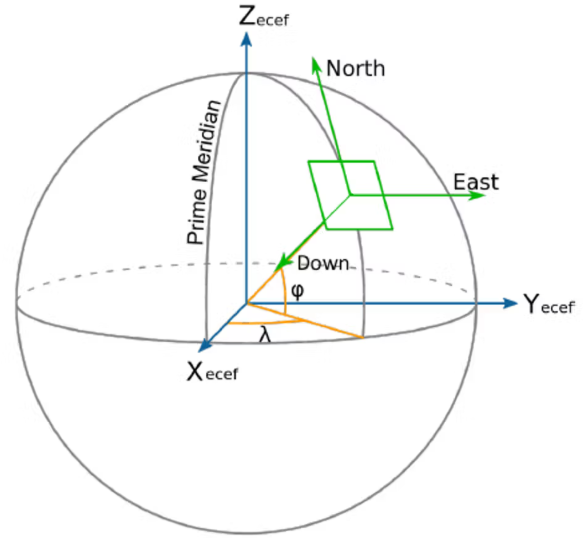
The NED (North, East, Down) frame is seen in the figure below. This is a local tangential frame fixed to the Earth's surface.
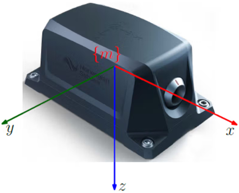
The MRU frame is the reference frame fixed to the MRU as seen in the figure below. All accelerometer and gyro raw measurements are performed in this frame.
The vessel's BODY frame is the frame fixed to the vessel as seen in the figure below, which also shows the NED and MRU frames.
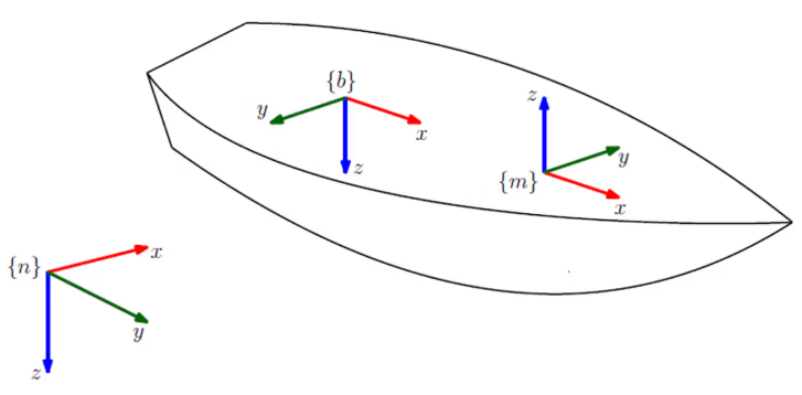
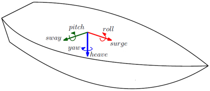
The MRU and Body frame rotate together as the MRU is mounted to the vessel. The attitude of the MRU with respect to the NED frame is measured by the MRU. The BODY frame of a vessel is a right hand coordinate system, with x-axis pointing forward and y-axis pointing to starboard. The MRU can output roll, pitch, yaw, surge, sway and heave motion measurements. The positive directions for these degrees of freedom are shown in the figure below.
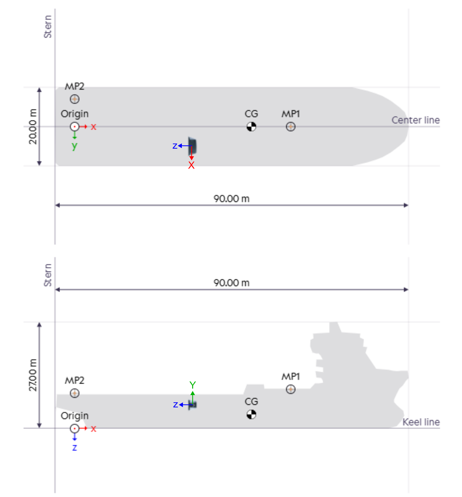
An example of an MRU mounted on a ship is shown in the figure below. The MRU is displayed with its reference frame, and the origin of the vessel’s BODY frame is located at the aft of the ship.
Rotation matrix and Euler angles
The rotation matrix from BODY to NED is %20%5Cin%20SO(3)%3C%2Ftitle%3E%0A%3Cdefs%20aria-hidden%3D%22true%22%3E%0A%3Cpath%20stroke-width%3D%221%22%20id%3D%22E1-MJMATHI-52%22%20d%3D%22M230%20637Q203%20637%20198%20638T193%20649Q193%20676%20204%20682Q206%20683%20378%20683Q550%20682%20564%20680Q620%20672%20658%20652T712%20606T733%20563T739%20529Q739%20484%20710%20445T643%20385T576%20351T538%20338L545%20333Q612%20295%20612%20223Q612%20212%20607%20162T602%2080V71Q602%2053%20603%2043T614%2025T640%2016Q668%2016%20686%2038T712%2085Q717%2099%20720%20102T735%20105Q755%20105%20755%2093Q755%2075%20731%2036Q693%20-21%20641%20-21H632Q571%20-21%20531%204T487%2082Q487%20109%20502%20166T517%20239Q517%20290%20474%20313Q459%20320%20449%20321T378%20323H309L277%20193Q244%2061%20244%2059Q244%2055%20245%2054T252%2050T269%2048T302%2046H333Q339%2038%20339%2037T336%2019Q332%206%20326%200H311Q275%202%20180%202Q146%202%20117%202T71%202T50%201Q33%201%2033%2010Q33%2012%2036%2024Q41%2043%2046%2045Q50%2046%2061%2046H67Q94%2046%20127%2049Q141%2052%20146%2061Q149%2065%20218%20339T287%20628Q287%20635%20230%20637ZM630%20554Q630%20586%20609%20608T523%20636Q521%20636%20500%20636T462%20637H440Q393%20637%20386%20627Q385%20624%20352%20494T319%20361Q319%20360%20388%20360Q466%20361%20492%20367Q556%20377%20592%20426Q608%20449%20619%20486T630%20554Z%22%3E%3C%2Fpath%3E%0A%3Cpath%20stroke-width%3D%221%22%20id%3D%22E1-MJMATHI-6E%22%20d%3D%22M21%20287Q22%20293%2024%20303T36%20341T56%20388T89%20425T135%20442Q171%20442%20195%20424T225%20390T231%20369Q231%20367%20232%20367L243%20378Q304%20442%20382%20442Q436%20442%20469%20415T503%20336T465%20179T427%2052Q427%2026%20444%2026Q450%2026%20453%2027Q482%2032%20505%2065T540%20145Q542%20153%20560%20153Q580%20153%20580%20145Q580%20144%20576%20130Q568%20101%20554%2073T508%2017T439%20-10Q392%20-10%20371%2017T350%2073Q350%2092%20386%20193T423%20345Q423%20404%20379%20404H374Q288%20404%20229%20303L222%20291L189%20157Q156%2026%20151%2016Q138%20-11%20108%20-11Q95%20-11%2087%20-5T76%207T74%2017Q74%2030%20112%20180T152%20343Q153%20348%20153%20366Q153%20405%20129%20405Q91%20405%2066%20305Q60%20285%2060%20284Q58%20278%2041%20278H27Q21%20284%2021%20287Z%22%3E%3C%2Fpath%3E%0A%3Cpath%20stroke-width%3D%221%22%20id%3D%22E1-MJMATHI-62%22%20d%3D%22M73%20647Q73%20657%2077%20670T89%20683Q90%20683%20161%20688T234%20694Q246%20694%20246%20685T212%20542Q204%20508%20195%20472T180%20418L176%20399Q176%20396%20182%20402Q231%20442%20283%20442Q345%20442%20383%20396T422%20280Q422%20169%20343%2079T173%20-11Q123%20-11%2082%2027T40%20150V159Q40%20180%2048%20217T97%20414Q147%20611%20147%20623T109%20637Q104%20637%20101%20637H96Q86%20637%2083%20637T76%20640T73%20647ZM336%20325V331Q336%20405%20275%20405Q258%20405%20240%20397T207%20376T181%20352T163%20330L157%20322L136%20236Q114%20150%20114%20114Q114%2066%20138%2042Q154%2026%20178%2026Q211%2026%20245%2058Q270%2081%20285%20114T318%20219Q336%20291%20336%20325Z%22%3E%3C%2Fpath%3E%0A%3Cpath%20stroke-width%3D%221%22%20id%3D%22E1-MJMAIN-28%22%20d%3D%22M94%20250Q94%20319%20104%20381T127%20488T164%20576T202%20643T244%20695T277%20729T302%20750H315H319Q333%20750%20333%20741Q333%20738%20316%20720T275%20667T226%20581T184%20443T167%20250T184%2058T225%20-81T274%20-167T316%20-220T333%20-241Q333%20-250%20318%20-250H315H302L274%20-226Q180%20-141%20137%20-14T94%20250Z%22%3E%3C%2Fpath%3E%0A%3Cpath%20stroke-width%3D%221%22%20id%3D%22E1-MJMAIN-398%22%20d%3D%22M56%20340Q56%20423%2086%20494T164%20610T270%20680T388%20705Q521%20705%20621%20601T722%20341Q722%20260%20693%20191T617%2075T510%204T388%20-22T267%203T160%2074T85%20189T56%20340ZM610%20339Q610%20428%20590%20495T535%20598T463%20651T384%20668Q332%20668%20289%20638T221%20566Q168%20485%20168%20339Q168%20274%20176%20235Q189%20158%20228%20105T324%2028Q356%2016%20388%2016Q415%2016%20442%2024T501%2054T555%20111T594%20205T610%20339ZM223%20263V422H263V388H514V422H554V263H514V297H263V263H223Z%22%3E%3C%2Fpath%3E%0A%3Cpath%20stroke-width%3D%221%22%20id%3D%22E1-MJMAIN-29%22%20d%3D%22M60%20749L64%20750Q69%20750%2074%20750H86L114%20726Q208%20641%20251%20514T294%20250Q294%20182%20284%20119T261%2012T224%20-76T186%20-143T145%20-194T113%20-227T90%20-246Q87%20-249%2086%20-250H74Q66%20-250%2063%20-250T58%20-247T55%20-238Q56%20-237%2066%20-225Q221%20-64%20221%20250T66%20725Q56%20737%2055%20738Q55%20746%2060%20749Z%22%3E%3C%2Fpath%3E%0A%3Cpath%20stroke-width%3D%221%22%20id%3D%22E1-MJMAIN-2208%22%20d%3D%22M84%20250Q84%20372%20166%20450T360%20539Q361%20539%20377%20539T419%20540T469%20540H568Q583%20532%20583%20520Q583%20511%20570%20501L466%20500Q355%20499%20329%20494Q280%20482%20242%20458T183%20409T147%20354T129%20306T124%20272V270H568Q583%20262%20583%20250T568%20230H124V228Q124%20207%20134%20177T167%20112T231%2048T328%207Q355%201%20466%200H570Q583%20-10%20583%20-20Q583%20-32%20568%20-40H471Q464%20-40%20446%20-40T417%20-41Q262%20-41%20172%2045Q84%20127%2084%20250Z%22%3E%3C%2Fpath%3E%0A%3Cpath%20stroke-width%3D%221%22%20id%3D%22E1-MJMATHI-53%22%20d%3D%22M308%2024Q367%2024%20416%2076T466%20197Q466%20260%20414%20284Q308%20311%20278%20321T236%20341Q176%20383%20176%20462Q176%20523%20208%20573T273%20648Q302%20673%20343%20688T407%20704H418H425Q521%20704%20564%20640Q565%20640%20577%20653T603%20682T623%20704Q624%20704%20627%20704T632%20705Q645%20705%20645%20698T617%20577T585%20459T569%20456Q549%20456%20549%20465Q549%20471%20550%20475Q550%20478%20551%20494T553%20520Q553%20554%20544%20579T526%20616T501%20641Q465%20662%20419%20662Q362%20662%20313%20616T263%20510Q263%20480%20278%20458T319%20427Q323%20425%20389%20408T456%20390Q490%20379%20522%20342T554%20242Q554%20216%20546%20186Q541%20164%20528%20137T492%2078T426%2018T332%20-20Q320%20-22%20298%20-22Q199%20-22%20144%2033L134%2044L106%2013Q83%20-14%2078%20-18T65%20-22Q52%20-22%2052%20-14Q52%20-11%20110%20221Q112%20227%20130%20227H143Q149%20221%20149%20216Q149%20214%20148%20207T144%20186T142%20153Q144%20114%20160%2087T203%2047T255%2029T308%2024Z%22%3E%3C%2Fpath%3E%0A%3Cpath%20stroke-width%3D%221%22%20id%3D%22E1-MJMATHI-4F%22%20d%3D%22M740%20435Q740%20320%20676%20213T511%2042T304%20-22Q207%20-22%20138%2035T51%20201Q50%20209%2050%20244Q50%20346%2098%20438T227%20601Q351%20704%20476%20704Q514%20704%20524%20703Q621%20689%20680%20617T740%20435ZM637%20476Q637%20565%20591%20615T476%20665Q396%20665%20322%20605Q242%20542%20200%20428T157%20216Q157%20126%20200%2073T314%2019Q404%2019%20485%2098T608%20313Q637%20408%20637%20476Z%22%3E%3C%2Fpath%3E%0A%3Cpath%20stroke-width%3D%221%22%20id%3D%22E1-MJMAIN-33%22%20d%3D%22M127%20463Q100%20463%2085%20480T69%20524Q69%20579%20117%20622T233%20665Q268%20665%20277%20664Q351%20652%20390%20611T430%20522Q430%20470%20396%20421T302%20350L299%20348Q299%20347%20308%20345T337%20336T375%20315Q457%20262%20457%20175Q457%2096%20395%2037T238%20-22Q158%20-22%20100%2021T42%20130Q42%20158%2060%20175T105%20193Q133%20193%20151%20175T169%20130Q169%20119%20166%20110T159%2094T148%2082T136%2074T126%2070T118%2067L114%2066Q165%2021%20238%2021Q293%2021%20321%2074Q338%20107%20338%20175V195Q338%20290%20274%20322Q259%20328%20213%20329L171%20330L168%20332Q166%20335%20166%20348Q166%20366%20174%20366Q202%20366%20232%20371Q266%20376%20294%20413T322%20525V533Q322%20590%20287%20612Q265%20626%20240%20626Q208%20626%20181%20615T143%20592T132%20580H135Q138%20579%20143%20578T153%20573T165%20566T175%20555T183%20540T186%20520Q186%20498%20172%20481T127%20463Z%22%3E%3C%2Fpath%3E%0A%3C%2Fdefs%3E%0A%3Cg%20stroke%3D%22currentColor%22%20fill%3D%22currentColor%22%20stroke-width%3D%220%22%20transform%3D%22matrix(1%200%200%20-1%200%200)%22%20aria-hidden%3D%22true%22%3E%0A%20%3Cuse%20xlink%3Ahref%3D%22%23E1-MJMATHI-52%22%20x%3D%220%22%20y%3D%220%22%3E%3C%2Fuse%3E%0A%20%3Cuse%20transform%3D%22scale(0.707)%22%20xlink%3Ahref%3D%22%23E1-MJMATHI-6E%22%20x%3D%221074%22%20y%3D%22499%22%3E%3C%2Fuse%3E%0A%20%3Cuse%20transform%3D%22scale(0.707)%22%20xlink%3Ahref%3D%22%23E1-MJMATHI-62%22%20x%3D%221074%22%20y%3D%22-463%22%3E%3C%2Fuse%3E%0A%20%3Cuse%20xlink%3Ahref%3D%22%23E1-MJMAIN-28%22%20x%3D%221284%22%20y%3D%220%22%3E%3C%2Fuse%3E%0A%3Cg%20transform%3D%22translate(1673%2C0)%22%3E%0A%20%3Cuse%20xlink%3Ahref%3D%22%23E1-MJMAIN-398%22%20x%3D%220%22%20y%3D%220%22%3E%3C%2Fuse%3E%0A%3Cg%20transform%3D%22translate(778%2C-150)%22%3E%0A%20%3Cuse%20transform%3D%22scale(0.707)%22%20xlink%3Ahref%3D%22%23E1-MJMATHI-6E%22%20x%3D%220%22%20y%3D%220%22%3E%3C%2Fuse%3E%0A%20%3Cuse%20transform%3D%22scale(0.707)%22%20xlink%3Ahref%3D%22%23E1-MJMATHI-62%22%20x%3D%22600%22%20y%3D%220%22%3E%3C%2Fuse%3E%0A%3C%2Fg%3E%0A%3C%2Fg%3E%0A%20%3Cuse%20xlink%3Ahref%3D%22%23E1-MJMAIN-29%22%20x%3D%223280%22%20y%3D%220%22%3E%3C%2Fuse%3E%0A%20%3Cuse%20xlink%3Ahref%3D%22%23E1-MJMAIN-2208%22%20x%3D%223947%22%20y%3D%220%22%3E%3C%2Fuse%3E%0A%20%3Cuse%20xlink%3Ahref%3D%22%23E1-MJMATHI-53%22%20x%3D%224892%22%20y%3D%220%22%3E%3C%2Fuse%3E%0A%20%3Cuse%20xlink%3Ahref%3D%22%23E1-MJMATHI-4F%22%20x%3D%225538%22%20y%3D%220%22%3E%3C%2Fuse%3E%0A%20%3Cuse%20xlink%3Ahref%3D%22%23E1-MJMAIN-28%22%20x%3D%226301%22%20y%3D%220%22%3E%3C%2Fuse%3E%0A%20%3Cuse%20xlink%3Ahref%3D%22%23E1-MJMAIN-33%22%20x%3D%226691%22%20y%3D%220%22%3E%3C%2Fuse%3E%0A%20%3Cuse%20xlink%3Ahref%3D%22%23E1-MJMAIN-29%22%20x%3D%227191%22%20y%3D%220%22%3E%3C%2Fuse%3E%0A%3C%2Fg%3E%0A%3C%2Fsvg%3E)
%20%3D%20R_%7Bz%2C%5Cpsi%7D%20R_%7By%2C%5Ctheta%7D%20R_%7Bx%2C%5Cphi%7D%2C%0A%5Cend%7Bequation%7D%3C%2Ftitle%3E%0A%3Cdefs%20aria-hidden%3D%22true%22%3E%0A%3Cpath%20stroke-width%3D%221%22%20id%3D%22E1-MJMATHI-52%22%20d%3D%22M230%20637Q203%20637%20198%20638T193%20649Q193%20676%20204%20682Q206%20683%20378%20683Q550%20682%20564%20680Q620%20672%20658%20652T712%20606T733%20563T739%20529Q739%20484%20710%20445T643%20385T576%20351T538%20338L545%20333Q612%20295%20612%20223Q612%20212%20607%20162T602%2080V71Q602%2053%20603%2043T614%2025T640%2016Q668%2016%20686%2038T712%2085Q717%2099%20720%20102T735%20105Q755%20105%20755%2093Q755%2075%20731%2036Q693%20-21%20641%20-21H632Q571%20-21%20531%204T487%2082Q487%20109%20502%20166T517%20239Q517%20290%20474%20313Q459%20320%20449%20321T378%20323H309L277%20193Q244%2061%20244%2059Q244%2055%20245%2054T252%2050T269%2048T302%2046H333Q339%2038%20339%2037T336%2019Q332%206%20326%200H311Q275%202%20180%202Q146%202%20117%202T71%202T50%201Q33%201%2033%2010Q33%2012%2036%2024Q41%2043%2046%2045Q50%2046%2061%2046H67Q94%2046%20127%2049Q141%2052%20146%2061Q149%2065%20218%20339T287%20628Q287%20635%20230%20637ZM630%20554Q630%20586%20609%20608T523%20636Q521%20636%20500%20636T462%20637H440Q393%20637%20386%20627Q385%20624%20352%20494T319%20361Q319%20360%20388%20360Q466%20361%20492%20367Q556%20377%20592%20426Q608%20449%20619%20486T630%20554Z%22%3E%3C%2Fpath%3E%0A%3Cpath%20stroke-width%3D%221%22%20id%3D%22E1-MJMATHI-6E%22%20d%3D%22M21%20287Q22%20293%2024%20303T36%20341T56%20388T89%20425T135%20442Q171%20442%20195%20424T225%20390T231%20369Q231%20367%20232%20367L243%20378Q304%20442%20382%20442Q436%20442%20469%20415T503%20336T465%20179T427%2052Q427%2026%20444%2026Q450%2026%20453%2027Q482%2032%20505%2065T540%20145Q542%20153%20560%20153Q580%20153%20580%20145Q580%20144%20576%20130Q568%20101%20554%2073T508%2017T439%20-10Q392%20-10%20371%2017T350%2073Q350%2092%20386%20193T423%20345Q423%20404%20379%20404H374Q288%20404%20229%20303L222%20291L189%20157Q156%2026%20151%2016Q138%20-11%20108%20-11Q95%20-11%2087%20-5T76%207T74%2017Q74%2030%20112%20180T152%20343Q153%20348%20153%20366Q153%20405%20129%20405Q91%20405%2066%20305Q60%20285%2060%20284Q58%20278%2041%20278H27Q21%20284%2021%20287Z%22%3E%3C%2Fpath%3E%0A%3Cpath%20stroke-width%3D%221%22%20id%3D%22E1-MJMATHI-62%22%20d%3D%22M73%20647Q73%20657%2077%20670T89%20683Q90%20683%20161%20688T234%20694Q246%20694%20246%20685T212%20542Q204%20508%20195%20472T180%20418L176%20399Q176%20396%20182%20402Q231%20442%20283%20442Q345%20442%20383%20396T422%20280Q422%20169%20343%2079T173%20-11Q123%20-11%2082%2027T40%20150V159Q40%20180%2048%20217T97%20414Q147%20611%20147%20623T109%20637Q104%20637%20101%20637H96Q86%20637%2083%20637T76%20640T73%20647ZM336%20325V331Q336%20405%20275%20405Q258%20405%20240%20397T207%20376T181%20352T163%20330L157%20322L136%20236Q114%20150%20114%20114Q114%2066%20138%2042Q154%2026%20178%2026Q211%2026%20245%2058Q270%2081%20285%20114T318%20219Q336%20291%20336%20325Z%22%3E%3C%2Fpath%3E%0A%3Cpath%20stroke-width%3D%221%22%20id%3D%22E1-MJMAIN-28%22%20d%3D%22M94%20250Q94%20319%20104%20381T127%20488T164%20576T202%20643T244%20695T277%20729T302%20750H315H319Q333%20750%20333%20741Q333%20738%20316%20720T275%20667T226%20581T184%20443T167%20250T184%2058T225%20-81T274%20-167T316%20-220T333%20-241Q333%20-250%20318%20-250H315H302L274%20-226Q180%20-141%20137%20-14T94%20250Z%22%3E%3C%2Fpath%3E%0A%3Cpath%20stroke-width%3D%221%22%20id%3D%22E1-MJMAIN-398%22%20d%3D%22M56%20340Q56%20423%2086%20494T164%20610T270%20680T388%20705Q521%20705%20621%20601T722%20341Q722%20260%20693%20191T617%2075T510%204T388%20-22T267%203T160%2074T85%20189T56%20340ZM610%20339Q610%20428%20590%20495T535%20598T463%20651T384%20668Q332%20668%20289%20638T221%20566Q168%20485%20168%20339Q168%20274%20176%20235Q189%20158%20228%20105T324%2028Q356%2016%20388%2016Q415%2016%20442%2024T501%2054T555%20111T594%20205T610%20339ZM223%20263V422H263V388H514V422H554V263H514V297H263V263H223Z%22%3E%3C%2Fpath%3E%0A%3Cpath%20stroke-width%3D%221%22%20id%3D%22E1-MJMAIN-29%22%20d%3D%22M60%20749L64%20750Q69%20750%2074%20750H86L114%20726Q208%20641%20251%20514T294%20250Q294%20182%20284%20119T261%2012T224%20-76T186%20-143T145%20-194T113%20-227T90%20-246Q87%20-249%2086%20-250H74Q66%20-250%2063%20-250T58%20-247T55%20-238Q56%20-237%2066%20-225Q221%20-64%20221%20250T66%20725Q56%20737%2055%20738Q55%20746%2060%20749Z%22%3E%3C%2Fpath%3E%0A%3Cpath%20stroke-width%3D%221%22%20id%3D%22E1-MJMAIN-3D%22%20d%3D%22M56%20347Q56%20360%2070%20367H707Q722%20359%20722%20347Q722%20336%20708%20328L390%20327H72Q56%20332%2056%20347ZM56%20153Q56%20168%2072%20173H708Q722%20163%20722%20153Q722%20140%20707%20133H70Q56%20140%2056%20153Z%22%3E%3C%2Fpath%3E%0A%3Cpath%20stroke-width%3D%221%22%20id%3D%22E1-MJMATHI-7A%22%20d%3D%22M347%20338Q337%20338%20294%20349T231%20360Q211%20360%20197%20356T174%20346T162%20335T155%20324L153%20320Q150%20317%20138%20317Q117%20317%20117%20325Q117%20330%20120%20339Q133%20378%20163%20406T229%20440Q241%20442%20246%20442Q271%20442%20291%20425T329%20392T367%20375Q389%20375%20411%20408T434%20441Q435%20442%20449%20442H462Q468%20436%20468%20434Q468%20430%20463%20420T449%20399T432%20377T418%20358L411%20349Q368%20298%20275%20214T160%20106L148%2094L163%2093Q185%2093%20227%2082T290%2071Q328%2071%20360%2090T402%20140Q406%20149%20409%20151T424%20153Q443%20153%20443%20143Q443%20138%20442%20134Q425%2072%20376%2031T278%20-11Q252%20-11%20232%206T193%2040T155%2057Q111%2057%2076%20-3Q70%20-11%2059%20-11H54H41Q35%20-5%2035%20-2Q35%2013%2093%2084Q132%20129%20225%20214T340%20322Q352%20338%20347%20338Z%22%3E%3C%2Fpath%3E%0A%3Cpath%20stroke-width%3D%221%22%20id%3D%22E1-MJMAIN-2C%22%20d%3D%22M78%2035T78%2060T94%20103T137%20121Q165%20121%20187%2096T210%208Q210%20-27%20201%20-60T180%20-117T154%20-158T130%20-185T117%20-194Q113%20-194%20104%20-185T95%20-172Q95%20-168%20106%20-156T131%20-126T157%20-76T173%20-3V9L172%208Q170%207%20167%206T161%203T152%201T140%200Q113%200%2096%2017Z%22%3E%3C%2Fpath%3E%0A%3Cpath%20stroke-width%3D%221%22%20id%3D%22E1-MJMATHI-3C8%22%20d%3D%22M161%20441Q202%20441%20226%20417T250%20358Q250%20338%20218%20252T187%20127Q190%2085%20214%2061Q235%2043%20257%2037Q275%2029%20288%2029H289L371%20360Q455%20691%20456%20692Q459%20694%20472%20694Q492%20694%20492%20687Q492%20678%20411%20356Q329%2028%20329%2027T335%2026Q421%2026%20498%20114T576%20278Q576%20302%20568%20319T550%20343T532%20361T524%20384Q524%20405%20541%20424T583%20443Q602%20443%20618%20425T634%20366Q634%20337%20623%20288T605%20220Q573%20125%20492%2057T329%20-11H319L296%20-104Q272%20-198%20272%20-199Q270%20-205%20252%20-205H239Q233%20-199%20233%20-197Q233%20-192%20256%20-102T279%20-9Q272%20-8%20265%20-8Q106%2014%20106%20139Q106%20174%20139%20264T173%20379Q173%20380%20173%20381Q173%20390%20173%20393T169%20400T158%20404H154Q131%20404%20112%20385T82%20344T65%20302T57%20280Q55%20278%2041%20278H27Q21%20284%2021%20287Q21%20299%2034%20333T82%20404T161%20441Z%22%3E%3C%2Fpath%3E%0A%3Cpath%20stroke-width%3D%221%22%20id%3D%22E1-MJMATHI-79%22%20d%3D%22M21%20287Q21%20301%2036%20335T84%20406T158%20442Q199%20442%20224%20419T250%20355Q248%20336%20247%20334Q247%20331%20231%20288T198%20191T182%20105Q182%2062%20196%2045T238%2027Q261%2027%20281%2038T312%2061T339%2094Q339%2095%20344%20114T358%20173T377%20247Q415%20397%20419%20404Q432%20431%20462%20431Q475%20431%20483%20424T494%20412T496%20403Q496%20390%20447%20193T391%20-23Q363%20-106%20294%20-155T156%20-205Q111%20-205%2077%20-183T43%20-117Q43%20-95%2050%20-80T69%20-58T89%20-48T106%20-45Q150%20-45%20150%20-87Q150%20-107%20138%20-122T115%20-142T102%20-147L99%20-148Q101%20-153%20118%20-160T152%20-167H160Q177%20-167%20186%20-165Q219%20-156%20247%20-127T290%20-65T313%20-9T321%2021L315%2017Q309%2013%20296%206T270%20-6Q250%20-11%20231%20-11Q185%20-11%20150%2011T104%2082Q103%2089%20103%20113Q103%20170%20138%20262T173%20379Q173%20380%20173%20381Q173%20390%20173%20393T169%20400T158%20404H154Q131%20404%20112%20385T82%20344T65%20302T57%20280Q55%20278%2041%20278H27Q21%20284%2021%20287Z%22%3E%3C%2Fpath%3E%0A%3Cpath%20stroke-width%3D%221%22%20id%3D%22E1-MJMATHI-3B8%22%20d%3D%22M35%20200Q35%20302%2074%20415T180%20610T319%20704Q320%20704%20327%20704T339%20705Q393%20701%20423%20656Q462%20596%20462%20495Q462%20380%20417%20261T302%2066T168%20-10H161Q125%20-10%2099%2010T60%2063T41%20130T35%20200ZM383%20566Q383%20668%20330%20668Q294%20668%20260%20623T204%20521T170%20421T157%20371Q206%20370%20254%20370L351%20371Q352%20372%20359%20404T375%20484T383%20566ZM113%20132Q113%2026%20166%2026Q181%2026%20198%2036T239%2074T287%20161T335%20307L340%20324H145Q145%20321%20136%20286T120%20208T113%20132Z%22%3E%3C%2Fpath%3E%0A%3Cpath%20stroke-width%3D%221%22%20id%3D%22E1-MJMATHI-78%22%20d%3D%22M52%20289Q59%20331%20106%20386T222%20442Q257%20442%20286%20424T329%20379Q371%20442%20430%20442Q467%20442%20494%20420T522%20361Q522%20332%20508%20314T481%20292T458%20288Q439%20288%20427%20299T415%20328Q415%20374%20465%20391Q454%20404%20425%20404Q412%20404%20406%20402Q368%20386%20350%20336Q290%20115%20290%2078Q290%2050%20306%2038T341%2026Q378%2026%20414%2059T463%20140Q466%20150%20469%20151T485%20153H489Q504%20153%20504%20145Q504%20144%20502%20134Q486%2077%20440%2033T333%20-11Q263%20-11%20227%2052Q186%20-10%20133%20-10H127Q78%20-10%2057%2016T35%2071Q35%20103%2054%20123T99%20143Q142%20143%20142%20101Q142%2081%20130%2066T107%2046T94%2041L91%2040Q91%2039%2097%2036T113%2029T132%2026Q168%2026%20194%2071Q203%2087%20217%20139T245%20247T261%20313Q266%20340%20266%20352Q266%20380%20251%20392T217%20404Q177%20404%20142%20372T93%20290Q91%20281%2088%20280T72%20278H58Q52%20284%2052%20289Z%22%3E%3C%2Fpath%3E%0A%3Cpath%20stroke-width%3D%221%22%20id%3D%22E1-MJMATHI-3D5%22%20d%3D%22M409%20688Q413%20694%20421%20694H429H442Q448%20688%20448%20686Q448%20679%20418%20563Q411%20535%20404%20504T392%20458L388%20442Q388%20441%20397%20441T429%20435T477%20418Q521%20397%20550%20357T579%20260T548%20151T471%2065T374%2011T279%20-10H275L251%20-105Q245%20-128%20238%20-160Q230%20-192%20227%20-198T215%20-205H209Q189%20-205%20189%20-198Q189%20-193%20211%20-103L234%20-11Q234%20-10%20226%20-10Q221%20-10%20206%20-8T161%206T107%2036T62%2089T43%20171Q43%20231%2076%20284T157%20370T254%20422T342%20441Q347%20441%20348%20445L378%20567Q409%20686%20409%20688ZM122%20150Q122%20116%20134%2091T167%2053T203%2035T237%2027H244L337%20404Q333%20404%20326%20403T297%20395T255%20379T211%20350T170%20304Q152%20276%20137%20237Q122%20191%20122%20150ZM500%20282Q500%20320%20484%20347T444%20385T405%20400T381%20404H378L332%20217L284%2029Q284%2027%20285%2027Q293%2027%20317%2033T357%2047Q400%2066%20431%20100T475%20170T494%20234T500%20282Z%22%3E%3C%2Fpath%3E%0A%3C%2Fdefs%3E%0A%3Cg%20stroke%3D%22currentColor%22%20fill%3D%22currentColor%22%20stroke-width%3D%220%22%20transform%3D%22matrix(1%200%200%20-1%200%200)%22%20aria-hidden%3D%22true%22%3E%0A%20%3Cuse%20xlink%3Ahref%3D%22%23E1-MJMATHI-52%22%20x%3D%220%22%20y%3D%220%22%3E%3C%2Fuse%3E%0A%20%3Cuse%20transform%3D%22scale(0.707)%22%20xlink%3Ahref%3D%22%23E1-MJMATHI-6E%22%20x%3D%221074%22%20y%3D%22499%22%3E%3C%2Fuse%3E%0A%20%3Cuse%20transform%3D%22scale(0.707)%22%20xlink%3Ahref%3D%22%23E1-MJMATHI-62%22%20x%3D%221074%22%20y%3D%22-463%22%3E%3C%2Fuse%3E%0A%20%3Cuse%20xlink%3Ahref%3D%22%23E1-MJMAIN-28%22%20x%3D%221284%22%20y%3D%220%22%3E%3C%2Fuse%3E%0A%3Cg%20transform%3D%22translate(1673%2C0)%22%3E%0A%20%3Cuse%20xlink%3Ahref%3D%22%23E1-MJMAIN-398%22%20x%3D%220%22%20y%3D%220%22%3E%3C%2Fuse%3E%0A%3Cg%20transform%3D%22translate(778%2C-150)%22%3E%0A%20%3Cuse%20transform%3D%22scale(0.707)%22%20xlink%3Ahref%3D%22%23E1-MJMATHI-6E%22%20x%3D%220%22%20y%3D%220%22%3E%3C%2Fuse%3E%0A%20%3Cuse%20transform%3D%22scale(0.707)%22%20xlink%3Ahref%3D%22%23E1-MJMATHI-62%22%20x%3D%22600%22%20y%3D%220%22%3E%3C%2Fuse%3E%0A%3C%2Fg%3E%0A%3C%2Fg%3E%0A%20%3Cuse%20xlink%3Ahref%3D%22%23E1-MJMAIN-29%22%20x%3D%223280%22%20y%3D%220%22%3E%3C%2Fuse%3E%0A%20%3Cuse%20xlink%3Ahref%3D%22%23E1-MJMAIN-3D%22%20x%3D%223947%22%20y%3D%220%22%3E%3C%2Fuse%3E%0A%3Cg%20transform%3D%22translate(5003%2C0)%22%3E%0A%20%3Cuse%20xlink%3Ahref%3D%22%23E1-MJMATHI-52%22%20x%3D%220%22%20y%3D%220%22%3E%3C%2Fuse%3E%0A%3Cg%20transform%3D%22translate(759%2C-150)%22%3E%0A%20%3Cuse%20transform%3D%22scale(0.707)%22%20xlink%3Ahref%3D%22%23E1-MJMATHI-7A%22%20x%3D%220%22%20y%3D%220%22%3E%3C%2Fuse%3E%0A%20%3Cuse%20transform%3D%22scale(0.707)%22%20xlink%3Ahref%3D%22%23E1-MJMAIN-2C%22%20x%3D%22468%22%20y%3D%220%22%3E%3C%2Fuse%3E%0A%20%3Cuse%20transform%3D%22scale(0.707)%22%20xlink%3Ahref%3D%22%23E1-MJMATHI-3C8%22%20x%3D%22747%22%20y%3D%220%22%3E%3C%2Fuse%3E%0A%3C%2Fg%3E%0A%3C%2Fg%3E%0A%3Cg%20transform%3D%22translate(6852%2C0)%22%3E%0A%20%3Cuse%20xlink%3Ahref%3D%22%23E1-MJMATHI-52%22%20x%3D%220%22%20y%3D%220%22%3E%3C%2Fuse%3E%0A%3Cg%20transform%3D%22translate(759%2C-155)%22%3E%0A%20%3Cuse%20transform%3D%22scale(0.707)%22%20xlink%3Ahref%3D%22%23E1-MJMATHI-79%22%20x%3D%220%22%20y%3D%220%22%3E%3C%2Fuse%3E%0A%20%3Cuse%20transform%3D%22scale(0.707)%22%20xlink%3Ahref%3D%22%23E1-MJMAIN-2C%22%20x%3D%22497%22%20y%3D%220%22%3E%3C%2Fuse%3E%0A%20%3Cuse%20transform%3D%22scale(0.707)%22%20xlink%3Ahref%3D%22%23E1-MJMATHI-3B8%22%20x%3D%22776%22%20y%3D%220%22%3E%3C%2Fuse%3E%0A%3C%2Fg%3E%0A%3C%2Fg%3E%0A%3Cg%20transform%3D%22translate(8592%2C0)%22%3E%0A%20%3Cuse%20xlink%3Ahref%3D%22%23E1-MJMATHI-52%22%20x%3D%220%22%20y%3D%220%22%3E%3C%2Fuse%3E%0A%3Cg%20transform%3D%22translate(759%2C-150)%22%3E%0A%20%3Cuse%20transform%3D%22scale(0.707)%22%20xlink%3Ahref%3D%22%23E1-MJMATHI-78%22%20x%3D%220%22%20y%3D%220%22%3E%3C%2Fuse%3E%0A%20%3Cuse%20transform%3D%22scale(0.707)%22%20xlink%3Ahref%3D%22%23E1-MJMAIN-2C%22%20x%3D%22572%22%20y%3D%220%22%3E%3C%2Fuse%3E%0A%20%3Cuse%20transform%3D%22scale(0.707)%22%20xlink%3Ahref%3D%22%23E1-MJMATHI-3D5%22%20x%3D%22851%22%20y%3D%220%22%3E%3C%2Fuse%3E%0A%3C%2Fg%3E%0A%3C%2Fg%3E%0A%20%3Cuse%20xlink%3Ahref%3D%22%23E1-MJMAIN-2C%22%20x%3D%2210475%22%20y%3D%220%22%3E%3C%2Fuse%3E%0A%3C%2Fg%3E%0A%3C%2Fsvg%3E)
where
%22%20aria-hidden%3D%22true%22%3E%0A%20%3Cuse%20xlink%3Ahref%3D%22%23E1-MJMATHI-52%22%20x%3D%220%22%20y%3D%220%22%3E%3C%2Fuse%3E%0A%3Cg%20transform%3D%22translate(759%2C-150)%22%3E%0A%20%3Cuse%20transform%3D%22scale(0.707)%22%20xlink%3Ahref%3D%22%23E1-MJMATHI-78%22%20x%3D%220%22%20y%3D%220%22%3E%3C%2Fuse%3E%0A%20%3Cuse%20transform%3D%22scale(0.707)%22%20xlink%3Ahref%3D%22%23E1-MJMAIN-2C%22%20x%3D%22572%22%20y%3D%220%22%3E%3C%2Fuse%3E%0A%20%3Cuse%20transform%3D%22scale(0.707)%22%20xlink%3Ahref%3D%22%23E1-MJMATHI-3D5%22%20x%3D%22851%22%20y%3D%220%22%3E%3C%2Fuse%3E%0A%3C%2Fg%3E%0A%20%3Cuse%20xlink%3Ahref%3D%22%23E1-MJMAIN-3D%22%20x%3D%222160%22%20y%3D%220%22%3E%3C%2Fuse%3E%0A%3Cg%20transform%3D%22translate(3217%2C0)%22%3E%0A%3Cg%20transform%3D%22translate(0%2C2156)%22%3E%0A%20%3Cuse%20xlink%3Ahref%3D%22%23E1-MJSZ4-23A1%22%20x%3D%220%22%20y%3D%22-1155%22%3E%3C%2Fuse%3E%0A%3Cg%20transform%3D%22translate(0%2C-2060.4867549668875)%20scale(1%2C0.5132450331125827)%22%3E%0A%20%3Cuse%20xlink%3Ahref%3D%22%23E1-MJSZ4-23A2%22%3E%3C%2Fuse%3E%0A%3C%2Fg%3E%0A%20%3Cuse%20xlink%3Ahref%3D%22%23E1-MJSZ4-23A3%22%20x%3D%220%22%20y%3D%22-3167%22%3E%3C%2Fuse%3E%0A%3C%2Fg%3E%0A%3Cg%20transform%3D%22translate(834%2C0)%22%3E%0A%3Cg%20transform%3D%22translate(-11%2C0)%22%3E%0A%20%3Cuse%20xlink%3Ahref%3D%22%23E1-MJMAIN-31%22%20x%3D%220%22%20y%3D%221356%22%3E%3C%2Fuse%3E%0A%20%3Cuse%20xlink%3Ahref%3D%22%23E1-MJMAIN-30%22%20x%3D%220%22%20y%3D%22-44%22%3E%3C%2Fuse%3E%0A%20%3Cuse%20xlink%3Ahref%3D%22%23E1-MJMAIN-30%22%20x%3D%220%22%20y%3D%22-1450%22%3E%3C%2Fuse%3E%0A%3C%2Fg%3E%0A%3Cg%20transform%3D%22translate(1490%2C0)%22%3E%0A%20%3Cuse%20xlink%3Ahref%3D%22%23E1-MJMAIN-30%22%20x%3D%22282%22%20y%3D%221356%22%3E%3C%2Fuse%3E%0A%3Cg%20transform%3D%22translate(18%2C-44)%22%3E%0A%20%3Cuse%20xlink%3Ahref%3D%22%23E1-MJMATHI-63%22%20x%3D%220%22%20y%3D%220%22%3E%3C%2Fuse%3E%0A%20%3Cuse%20xlink%3Ahref%3D%22%23E1-MJMATHI-3D5%22%20x%3D%22433%22%20y%3D%220%22%3E%3C%2Fuse%3E%0A%3C%2Fg%3E%0A%3Cg%20transform%3D%22translate(0%2C-1450)%22%3E%0A%20%3Cuse%20xlink%3Ahref%3D%22%23E1-MJMATHI-73%22%20x%3D%220%22%20y%3D%220%22%3E%3C%2Fuse%3E%0A%20%3Cuse%20xlink%3Ahref%3D%22%23E1-MJMATHI-3D5%22%20x%3D%22469%22%20y%3D%220%22%3E%3C%2Fuse%3E%0A%3C%2Fg%3E%0A%3C%2Fg%3E%0A%3Cg%20transform%3D%22translate(3556%2C0)%22%3E%0A%20%3Cuse%20xlink%3Ahref%3D%22%23E1-MJMAIN-30%22%20x%3D%22672%22%20y%3D%221356%22%3E%3C%2Fuse%3E%0A%3Cg%20transform%3D%22translate(0%2C-44)%22%3E%0A%20%3Cuse%20xlink%3Ahref%3D%22%23E1-MJMAIN-2212%22%20x%3D%220%22%20y%3D%220%22%3E%3C%2Fuse%3E%0A%20%3Cuse%20xlink%3Ahref%3D%22%23E1-MJMATHI-73%22%20x%3D%22778%22%20y%3D%220%22%3E%3C%2Fuse%3E%0A%20%3Cuse%20xlink%3Ahref%3D%22%23E1-MJMATHI-3D5%22%20x%3D%221248%22%20y%3D%220%22%3E%3C%2Fuse%3E%0A%3C%2Fg%3E%0A%3Cg%20transform%3D%22translate(407%2C-1450)%22%3E%0A%20%3Cuse%20xlink%3Ahref%3D%22%23E1-MJMATHI-63%22%20x%3D%220%22%20y%3D%220%22%3E%3C%2Fuse%3E%0A%20%3Cuse%20xlink%3Ahref%3D%22%23E1-MJMATHI-3D5%22%20x%3D%22433%22%20y%3D%220%22%3E%3C%2Fuse%3E%0A%3C%2Fg%3E%0A%3C%2Fg%3E%0A%3C%2Fg%3E%0A%3Cg%20transform%3D%22translate(6402%2C2156)%22%3E%0A%20%3Cuse%20xlink%3Ahref%3D%22%23E1-MJSZ4-23A4%22%20x%3D%220%22%20y%3D%22-1155%22%3E%3C%2Fuse%3E%0A%3Cg%20transform%3D%22translate(0%2C-2060.4867549668875)%20scale(1%2C0.5132450331125827)%22%3E%0A%20%3Cuse%20xlink%3Ahref%3D%22%23E1-MJSZ4-23A5%22%3E%3C%2Fuse%3E%0A%3C%2Fg%3E%0A%20%3Cuse%20xlink%3Ahref%3D%22%23E1-MJSZ4-23A6%22%20x%3D%220%22%20y%3D%22-3167%22%3E%3C%2Fuse%3E%0A%3C%2Fg%3E%0A%3C%2Fg%3E%0A%20%3Cuse%20xlink%3Ahref%3D%22%23E1-MJMAIN-2C%22%20x%3D%2210453%22%20y%3D%220%22%3E%3C%2Fuse%3E%0A%3Cg%20transform%3D%22translate(11898%2C0)%22%3E%0A%20%3Cuse%20xlink%3Ahref%3D%22%23E1-MJMATHI-52%22%20x%3D%220%22%20y%3D%220%22%3E%3C%2Fuse%3E%0A%3Cg%20transform%3D%22translate(759%2C-155)%22%3E%0A%20%3Cuse%20transform%3D%22scale(0.707)%22%20xlink%3Ahref%3D%22%23E1-MJMATHI-79%22%20x%3D%220%22%20y%3D%220%22%3E%3C%2Fuse%3E%0A%20%3Cuse%20transform%3D%22scale(0.707)%22%20xlink%3Ahref%3D%22%23E1-MJMAIN-2C%22%20x%3D%22497%22%20y%3D%220%22%3E%3C%2Fuse%3E%0A%20%3Cuse%20transform%3D%22scale(0.707)%22%20xlink%3Ahref%3D%22%23E1-MJMATHI-3B8%22%20x%3D%22776%22%20y%3D%220%22%3E%3C%2Fuse%3E%0A%3C%2Fg%3E%0A%3C%2Fg%3E%0A%20%3Cuse%20xlink%3Ahref%3D%22%23E1-MJMAIN-3D%22%20x%3D%2213916%22%20y%3D%220%22%3E%3C%2Fuse%3E%0A%3Cg%20transform%3D%22translate(14972%2C0)%22%3E%0A%3Cg%20transform%3D%22translate(0%2C2150)%22%3E%0A%20%3Cuse%20xlink%3Ahref%3D%22%23E1-MJSZ4-23A1%22%20x%3D%220%22%20y%3D%22-1155%22%3E%3C%2Fuse%3E%0A%3Cg%20transform%3D%22translate(0%2C-2048.5066225165565)%20scale(1%2C0.49337748344370863)%22%3E%0A%20%3Cuse%20xlink%3Ahref%3D%22%23E1-MJSZ4-23A2%22%3E%3C%2Fuse%3E%0A%3C%2Fg%3E%0A%20%3Cuse%20xlink%3Ahref%3D%22%23E1-MJSZ4-23A3%22%20x%3D%220%22%20y%3D%22-3155%22%3E%3C%2Fuse%3E%0A%3C%2Fg%3E%0A%3Cg%20transform%3D%22translate(834%2C0)%22%3E%0A%3Cg%20transform%3D%22translate(-11%2C0)%22%3E%0A%3Cg%20transform%3D%22translate(407%2C1350)%22%3E%0A%20%3Cuse%20xlink%3Ahref%3D%22%23E1-MJMATHI-63%22%20x%3D%220%22%20y%3D%220%22%3E%3C%2Fuse%3E%0A%20%3Cuse%20xlink%3Ahref%3D%22%23E1-MJMATHI-3B8%22%20x%3D%22433%22%20y%3D%220%22%3E%3C%2Fuse%3E%0A%3C%2Fg%3E%0A%20%3Cuse%20xlink%3Ahref%3D%22%23E1-MJMAIN-30%22%20x%3D%22608%22%20y%3D%22-50%22%3E%3C%2Fuse%3E%0A%3Cg%20transform%3D%22translate(0%2C-1450)%22%3E%0A%20%3Cuse%20xlink%3Ahref%3D%22%23E1-MJMAIN-2212%22%20x%3D%220%22%20y%3D%220%22%3E%3C%2Fuse%3E%0A%20%3Cuse%20xlink%3Ahref%3D%22%23E1-MJMATHI-73%22%20x%3D%22778%22%20y%3D%220%22%3E%3C%2Fuse%3E%0A%20%3Cuse%20xlink%3Ahref%3D%22%23E1-MJMATHI-3B8%22%20x%3D%221248%22%20y%3D%220%22%3E%3C%2Fuse%3E%0A%3C%2Fg%3E%0A%3C%2Fg%3E%0A%3Cg%20transform%3D%22translate(2707%2C0)%22%3E%0A%20%3Cuse%20xlink%3Ahref%3D%22%23E1-MJMAIN-30%22%20x%3D%220%22%20y%3D%221350%22%3E%3C%2Fuse%3E%0A%20%3Cuse%20xlink%3Ahref%3D%22%23E1-MJMAIN-31%22%20x%3D%220%22%20y%3D%22-50%22%3E%3C%2Fuse%3E%0A%20%3Cuse%20xlink%3Ahref%3D%22%23E1-MJMAIN-30%22%20x%3D%220%22%20y%3D%22-1450%22%3E%3C%2Fuse%3E%0A%3C%2Fg%3E%0A%3Cg%20transform%3D%22translate(4207%2C0)%22%3E%0A%3Cg%20transform%3D%22translate(0%2C1350)%22%3E%0A%20%3Cuse%20xlink%3Ahref%3D%22%23E1-MJMATHI-73%22%20x%3D%220%22%20y%3D%220%22%3E%3C%2Fuse%3E%0A%20%3Cuse%20xlink%3Ahref%3D%22%23E1-MJMATHI-3B8%22%20x%3D%22469%22%20y%3D%220%22%3E%3C%2Fuse%3E%0A%3C%2Fg%3E%0A%20%3Cuse%20xlink%3Ahref%3D%22%23E1-MJMAIN-30%22%20x%3D%22219%22%20y%3D%22-50%22%3E%3C%2Fuse%3E%0A%3Cg%20transform%3D%22translate(18%2C-1450)%22%3E%0A%20%3Cuse%20xlink%3Ahref%3D%22%23E1-MJMATHI-63%22%20x%3D%220%22%20y%3D%220%22%3E%3C%2Fuse%3E%0A%20%3Cuse%20xlink%3Ahref%3D%22%23E1-MJMATHI-3B8%22%20x%3D%22433%22%20y%3D%220%22%3E%3C%2Fuse%3E%0A%3C%2Fg%3E%0A%3C%2Fg%3E%0A%3C%2Fg%3E%0A%3Cg%20transform%3D%22translate(6148%2C2150)%22%3E%0A%20%3Cuse%20xlink%3Ahref%3D%22%23E1-MJSZ4-23A4%22%20x%3D%220%22%20y%3D%22-1155%22%3E%3C%2Fuse%3E%0A%3Cg%20transform%3D%22translate(0%2C-2048.5066225165565)%20scale(1%2C0.49337748344370863)%22%3E%0A%20%3Cuse%20xlink%3Ahref%3D%22%23E1-MJSZ4-23A5%22%3E%3C%2Fuse%3E%0A%3C%2Fg%3E%0A%20%3Cuse%20xlink%3Ahref%3D%22%23E1-MJSZ4-23A6%22%20x%3D%220%22%20y%3D%22-3155%22%3E%3C%2Fuse%3E%0A%3C%2Fg%3E%0A%3C%2Fg%3E%0A%20%3Cuse%20xlink%3Ahref%3D%22%23E1-MJMAIN-2C%22%20x%3D%2221954%22%20y%3D%220%22%3E%3C%2Fuse%3E%0A%3Cg%20transform%3D%22translate(23400%2C0)%22%3E%0A%20%3Cuse%20xlink%3Ahref%3D%22%23E1-MJMATHI-52%22%20x%3D%220%22%20y%3D%220%22%3E%3C%2Fuse%3E%0A%3Cg%20transform%3D%22translate(759%2C-150)%22%3E%0A%20%3Cuse%20transform%3D%22scale(0.707)%22%20xlink%3Ahref%3D%22%23E1-MJMATHI-7A%22%20x%3D%220%22%20y%3D%220%22%3E%3C%2Fuse%3E%0A%20%3Cuse%20transform%3D%22scale(0.707)%22%20xlink%3Ahref%3D%22%23E1-MJMAIN-2C%22%20x%3D%22468%22%20y%3D%220%22%3E%3C%2Fuse%3E%0A%20%3Cuse%20transform%3D%22scale(0.707)%22%20xlink%3Ahref%3D%22%23E1-MJMATHI-3C8%22%20x%3D%22747%22%20y%3D%220%22%3E%3C%2Fuse%3E%0A%3C%2Fg%3E%0A%3C%2Fg%3E%0A%20%3Cuse%20xlink%3Ahref%3D%22%23E1-MJMAIN-3D%22%20x%3D%2225526%22%20y%3D%220%22%3E%3C%2Fuse%3E%0A%3Cg%20transform%3D%22translate(26582%2C0)%22%3E%0A%3Cg%20transform%3D%22translate(0%2C2156)%22%3E%0A%20%3Cuse%20xlink%3Ahref%3D%22%23E1-MJSZ4-23A1%22%20x%3D%220%22%20y%3D%22-1155%22%3E%3C%2Fuse%3E%0A%3Cg%20transform%3D%22translate(0%2C-2060.4867549668875)%20scale(1%2C0.5132450331125827)%22%3E%0A%20%3Cuse%20xlink%3Ahref%3D%22%23E1-MJSZ4-23A2%22%3E%3C%2Fuse%3E%0A%3C%2Fg%3E%0A%20%3Cuse%20xlink%3Ahref%3D%22%23E1-MJSZ4-23A3%22%20x%3D%220%22%20y%3D%22-3167%22%3E%3C%2Fuse%3E%0A%3C%2Fg%3E%0A%3Cg%20transform%3D%22translate(834%2C0)%22%3E%0A%3Cg%20transform%3D%22translate(-11%2C0)%22%3E%0A%3Cg%20transform%3D%22translate(18%2C1356)%22%3E%0A%20%3Cuse%20xlink%3Ahref%3D%22%23E1-MJMATHI-63%22%20x%3D%220%22%20y%3D%220%22%3E%3C%2Fuse%3E%0A%20%3Cuse%20xlink%3Ahref%3D%22%23E1-MJMATHI-3C8%22%20x%3D%22433%22%20y%3D%220%22%3E%3C%2Fuse%3E%0A%3C%2Fg%3E%0A%3Cg%20transform%3D%22translate(0%2C-50)%22%3E%0A%20%3Cuse%20xlink%3Ahref%3D%22%23E1-MJMATHI-73%22%20x%3D%220%22%20y%3D%220%22%3E%3C%2Fuse%3E%0A%20%3Cuse%20xlink%3Ahref%3D%22%23E1-MJMATHI-3C8%22%20x%3D%22469%22%20y%3D%220%22%3E%3C%2Fuse%3E%0A%3C%2Fg%3E%0A%20%3Cuse%20xlink%3Ahref%3D%22%23E1-MJMAIN-30%22%20x%3D%22310%22%20y%3D%22-1456%22%3E%3C%2Fuse%3E%0A%3C%2Fg%3E%0A%3Cg%20transform%3D%22translate(2110%2C0)%22%3E%0A%3Cg%20transform%3D%22translate(0%2C1356)%22%3E%0A%20%3Cuse%20xlink%3Ahref%3D%22%23E1-MJMAIN-2212%22%20x%3D%220%22%20y%3D%220%22%3E%3C%2Fuse%3E%0A%20%3Cuse%20xlink%3Ahref%3D%22%23E1-MJMATHI-73%22%20x%3D%22778%22%20y%3D%220%22%3E%3C%2Fuse%3E%0A%20%3Cuse%20xlink%3Ahref%3D%22%23E1-MJMATHI-3C8%22%20x%3D%221248%22%20y%3D%220%22%3E%3C%2Fuse%3E%0A%3C%2Fg%3E%0A%3Cg%20transform%3D%22translate(407%2C-50)%22%3E%0A%20%3Cuse%20xlink%3Ahref%3D%22%23E1-MJMATHI-63%22%20x%3D%220%22%20y%3D%220%22%3E%3C%2Fuse%3E%0A%20%3Cuse%20xlink%3Ahref%3D%22%23E1-MJMATHI-3C8%22%20x%3D%22433%22%20y%3D%220%22%3E%3C%2Fuse%3E%0A%3C%2Fg%3E%0A%20%3Cuse%20xlink%3Ahref%3D%22%23E1-MJMAIN-30%22%20x%3D%22699%22%20y%3D%22-1456%22%3E%3C%2Fuse%3E%0A%3C%2Fg%3E%0A%3Cg%20transform%3D%22translate(5010%2C0)%22%3E%0A%20%3Cuse%20xlink%3Ahref%3D%22%23E1-MJMAIN-30%22%20x%3D%220%22%20y%3D%221356%22%3E%3C%2Fuse%3E%0A%20%3Cuse%20xlink%3Ahref%3D%22%23E1-MJMAIN-30%22%20x%3D%220%22%20y%3D%22-50%22%3E%3C%2Fuse%3E%0A%20%3Cuse%20xlink%3Ahref%3D%22%23E1-MJMAIN-31%22%20x%3D%220%22%20y%3D%22-1456%22%3E%3C%2Fuse%3E%0A%3C%2Fg%3E%0A%3C%2Fg%3E%0A%3Cg%20transform%3D%22translate(6512%2C2156)%22%3E%0A%20%3Cuse%20xlink%3Ahref%3D%22%23E1-MJSZ4-23A4%22%20x%3D%220%22%20y%3D%22-1155%22%3E%3C%2Fuse%3E%0A%3Cg%20transform%3D%22translate(0%2C-2060.4867549668875)%20scale(1%2C0.5132450331125827)%22%3E%0A%20%3Cuse%20xlink%3Ahref%3D%22%23E1-MJSZ4-23A5%22%3E%3C%2Fuse%3E%0A%3C%2Fg%3E%0A%20%3Cuse%20xlink%3Ahref%3D%22%23E1-MJSZ4-23A6%22%20x%3D%220%22%20y%3D%22-3167%22%3E%3C%2Fuse%3E%0A%3C%2Fg%3E%0A%3C%2Fg%3E%0A%20%3Cuse%20xlink%3Ahref%3D%22%23E1-MJMAIN-2C%22%20x%3D%2233928%22%20y%3D%220%22%3E%3C%2Fuse%3E%0A%3C%2Fg%3E%0A%3C%2Fsvg%3E)
are the rotation matrices from roll, pitch and yaw, respectively. %22%20aria-hidden%3D%22true%22%3E%0A%20%3Cuse%20xlink%3Ahref%3D%22%23E1-MJMATHI-63%22%20x%3D%220%22%20y%3D%220%22%3E%3C%2Fuse%3E%0A%3C%2Fg%3E%0A%3C%2Fsvg%3E)
%22%20aria-hidden%3D%22true%22%3E%0A%20%3Cuse%20xlink%3Ahref%3D%22%23E1-MJMATHI-73%22%20x%3D%220%22%20y%3D%220%22%3E%3C%2Fuse%3E%0A%3C%2Fg%3E%0A%3C%2Fsvg%3E)
ZYX convention
Note that the order in which these three principal rotations are carried out is not arbitrary. We use the ZYX convention, which is common in guidance, navigation, and control applications.
Practical examples
Roll and pitch reference frames
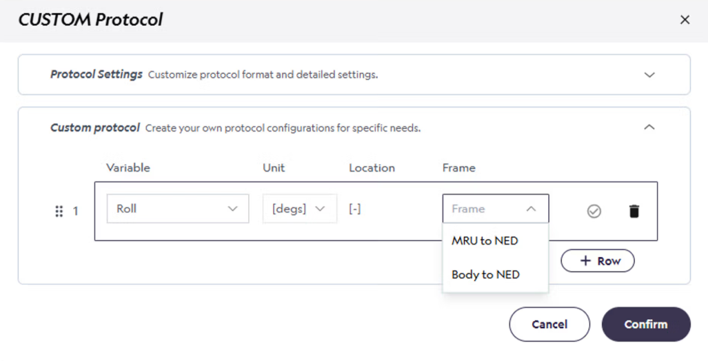
Roll and pitch are available in the MRU to NED and the BODY to NED frame. You can choose which frame when you define a custom protocol, see section below from the MRU configurator.
Heave, surge and sway reference frames
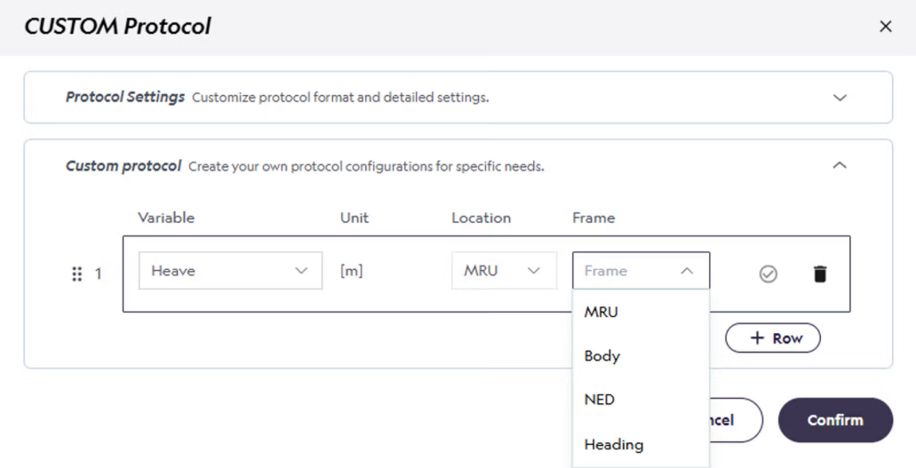
Heave, surge and sway are available in the MRU, BODY, NED and heading frames. You can choose which frame when you define a custom protocol, see section below from the MRU configurator.
MRU mounting - MRU vs body frame
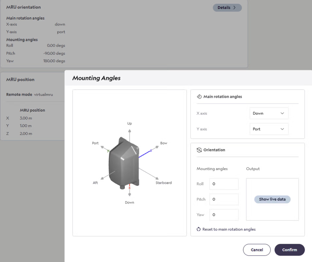
Use the MRU orientation settings in the MRU configurator to define the orientation of the MRU with respect to the vessel's axes. Note that you:
-
1. First define the main rotation angle of the MRU. In this case the MRU is mounted vertically with X-axis down and Y-axis to Port.
-
2. Secondly, you define the offset from the main rotation angle. This can be 0 if the MRU is perfectly vertical and aligned with the ships axes.
The resulting total mounting angles are: Roll = 0, pitch = -90 degrees and yaw = 180 degrees.
For detailed instructions on how to mount and align your MRU in the MRU configurator, see here.