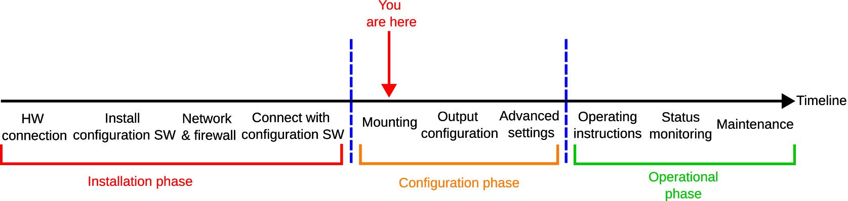
This guide provides step-by-step instructions for mounting and aligning your MRU. It consists of two main parts:
-
MRU orientation: Use the Orientation wizard to set the mounting orientation of the relative to the vessel (roll, pitch and yaw angles).
-
MRU position: Use the Position wizard to set the mounting position of the MRU, the monitoring points relative to the Survey Origin (SO) and the remote mode.
MRU configurator
Before getting started, you must download the Norwegian Subsea Configurator application (MRU configurator).
Part 1: MRU Orientation
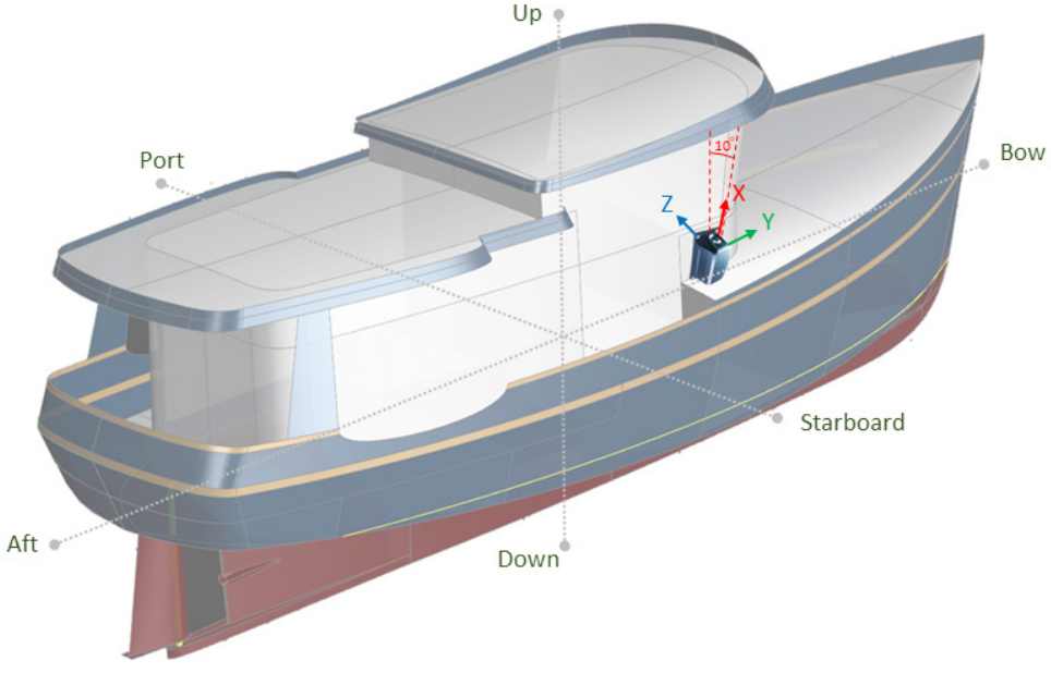
The procedure is illustrated with an example. An MRU is mounted on the vessel as shown below, with its x-axis slightly tilted outward toward the starboard side. The vessel axis system is defined as:
-
X-axis (Aft to Bow): Positive direction points toward the bow.
-
Y-axis (Port to Starboard): Positive direction points starboard.
-
Z-axis (Up to Down): Positive direction points downward.
For correct MRU orientation setup, do the following:
-
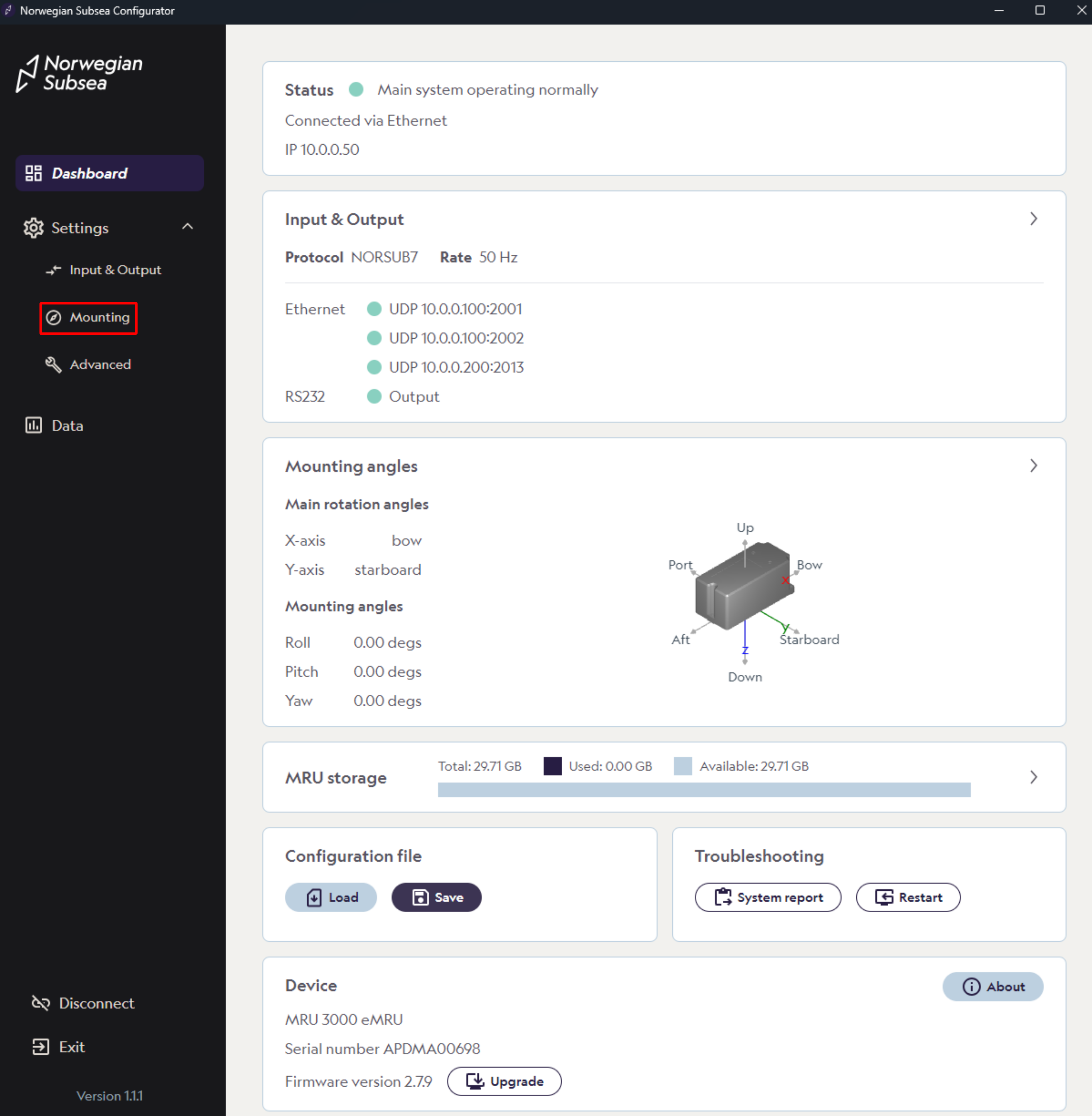
Open the MRU configurator and connect to your MRU
-
Click “Settings“->”Mounting” in the left bar
-
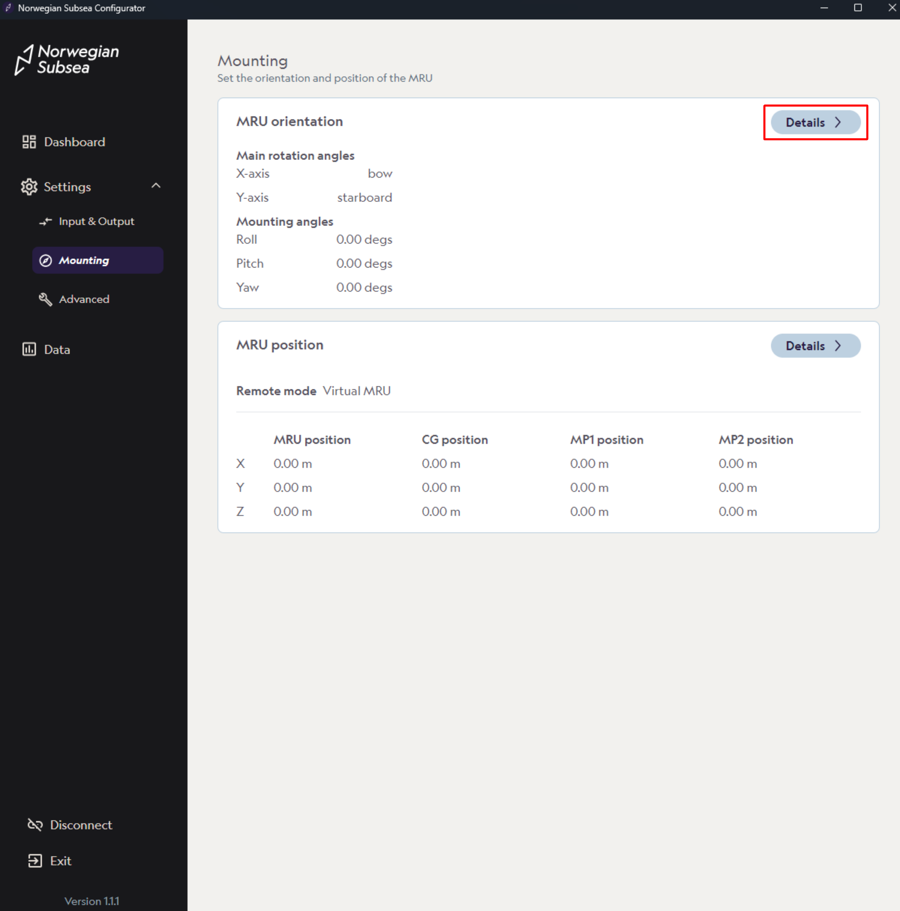
To set the orientation of the MRU, click “Details“ under the MRU orientation card.
-
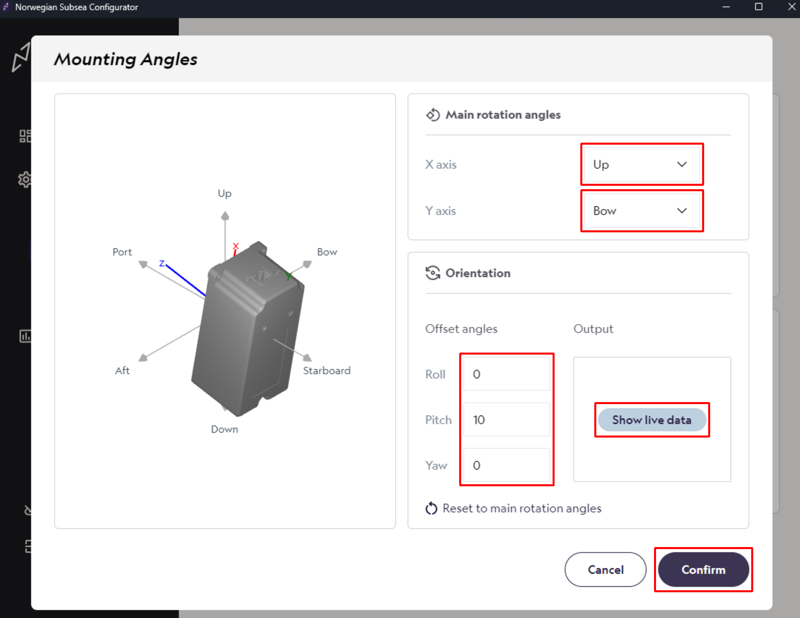
Here you can set the mounting orientation of the MRU relative to the vessel. The mounting angles are the result of two subsequent rotations:
-
1. Main rotation angles: First set the main rotation angles of the MRU relative to the vessel in 90 degrees steps (rough orientation).
-
2. Offset angles: Then set the offset angles between the main rotation frame and the MRU (fine alignment). Note that the MRU offset angles rotates the MRU about the new MRU frame set by the main rotation angles.
-
-
According to the mounting example, we modify the following:
-
Main rotation angles: Set x-axis to Up and y-axis to Bow.
-
Offset angles: Set roll angle to 0 degrees, pitch angle to 10 degrees and yaw angle to 0 degrees.
-
-
Click “Show Live Data” to view real-time MRU estimates of the mounting angles, measured in the MRU frame relative to the vessel (body) frame. Note that these angles are expressed as Euler angles using the ZYX convention.
-
Click “Confirm“ to set the mounting angles
-
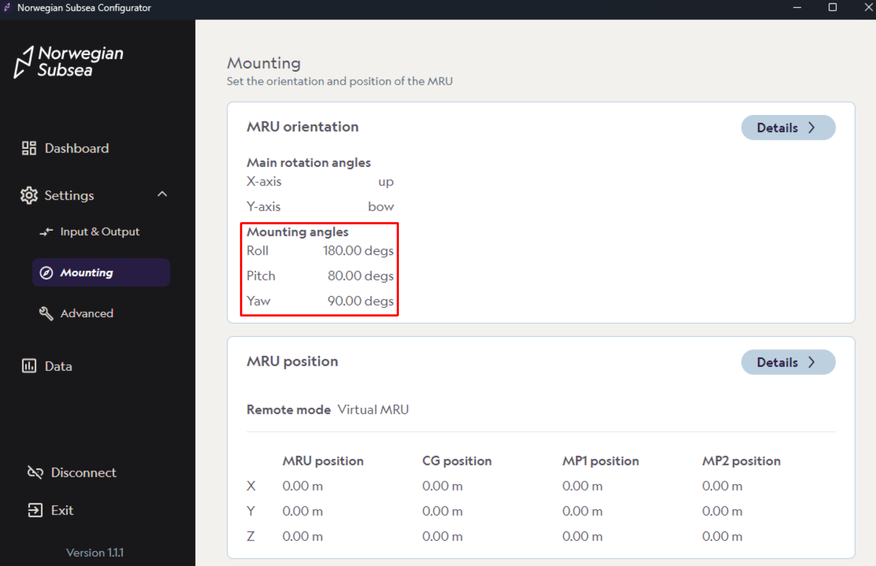
The resulting mounting angles relative to the vessel frame can be observed: roll = 180 degrees, pitch = 80 degrees, and yaw = 90 degrees. This represents the static rotation from the vessel (body) frame to the MRU frame, formed by the combination of the main rotation angles and the MRU offset angles. Note that the ZYX convention is used to represent this rotation.
Part 2: MRU position
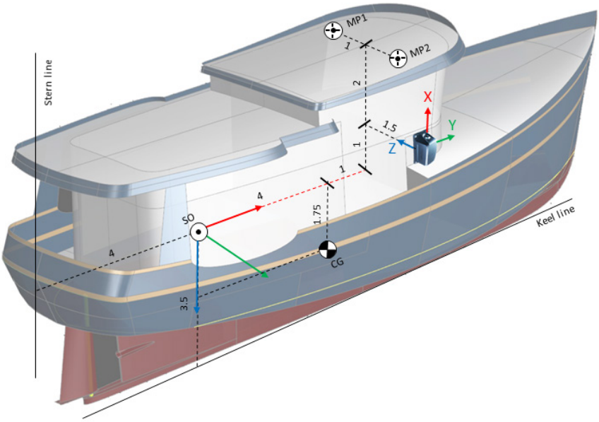
The MRU Position card is used to specify the positioning characteristics of the vessel, including the survey origin, the center of gravity position, the MRU position, and the monitoring points. Using the same vessel example, the MRU is mounted on the vessel as shown below, where:
-
Survey origin is located at -3.5 m to port from the keel line and 4 m forward from the stern line.
-
Center of gravity is located at [x, y, z] = [4, 0, 1.75] m relative to the survey origin.
-
MRU position is positioned at [x, y, z] = [5.0, 1.5, -1.0] m relative to the survey origin.
-
Monitoring point 1 is located at [x, y, z] = [6.0, -1.0, -3.0] m relative to the survey origin.
-
Monitoring point 2 is located at [x, y, z] = [6.0, 1.0, -3.0] m relative to the survey origin.
Survey origin
The Survey Origin correspond to the point in the vessel which is considered to be the reference point for the vessel frame: [x, y, z] = [0, 0, 0]. This is used to give a common reference to all the devices mounted on the vessel itself and should be already specified in the documentation for the equipment already installed on board. This point is usually defined with respect to the physical elements of the ship (keel, stern and center lines).
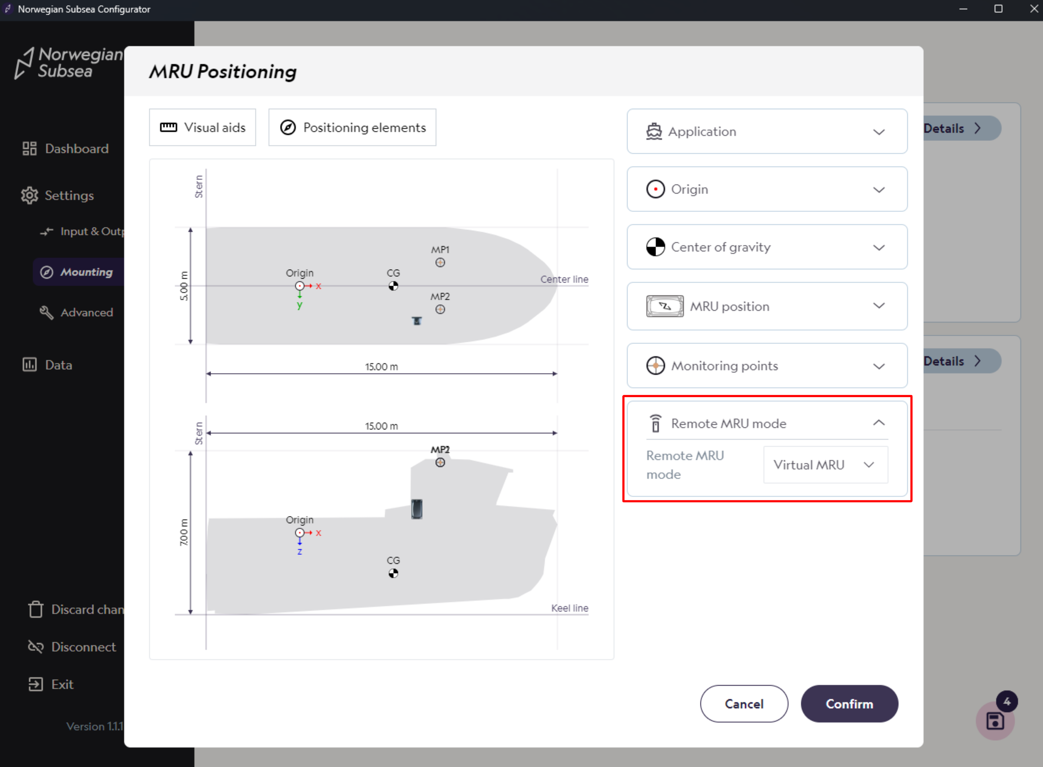
In addition, the MRU can be configured in two different remote modes:
-
Virtual MRU: When the remote mode is set to Virtual MRU, the output for the remote monitoring point is as if the MRU had been placed at that point (zero average surge, sway and heave position).
-
Projection: In Projection mode, the offset arm and displacement due to static roll/pitch are included in the output for the remote monitoring point.
-
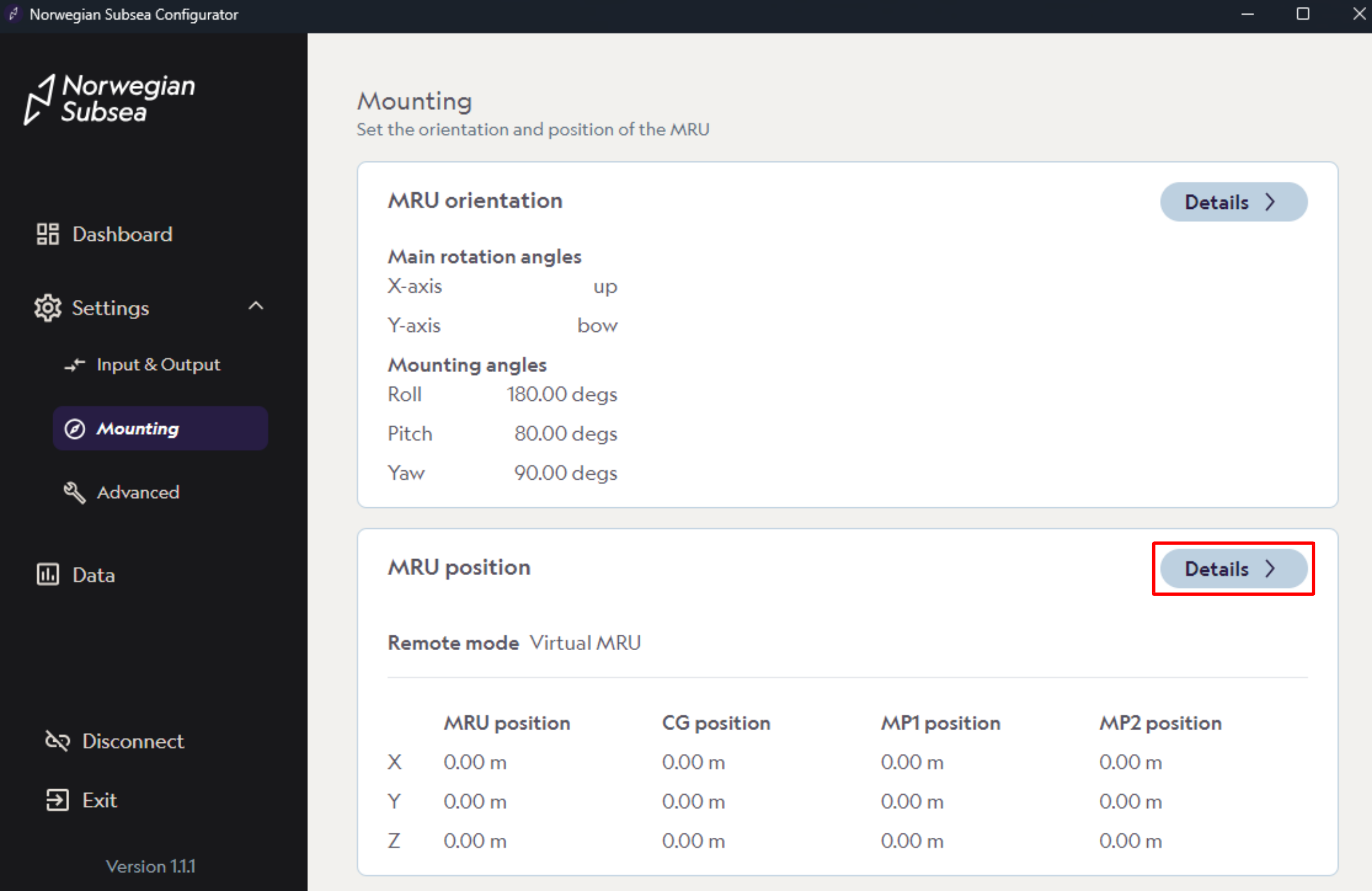
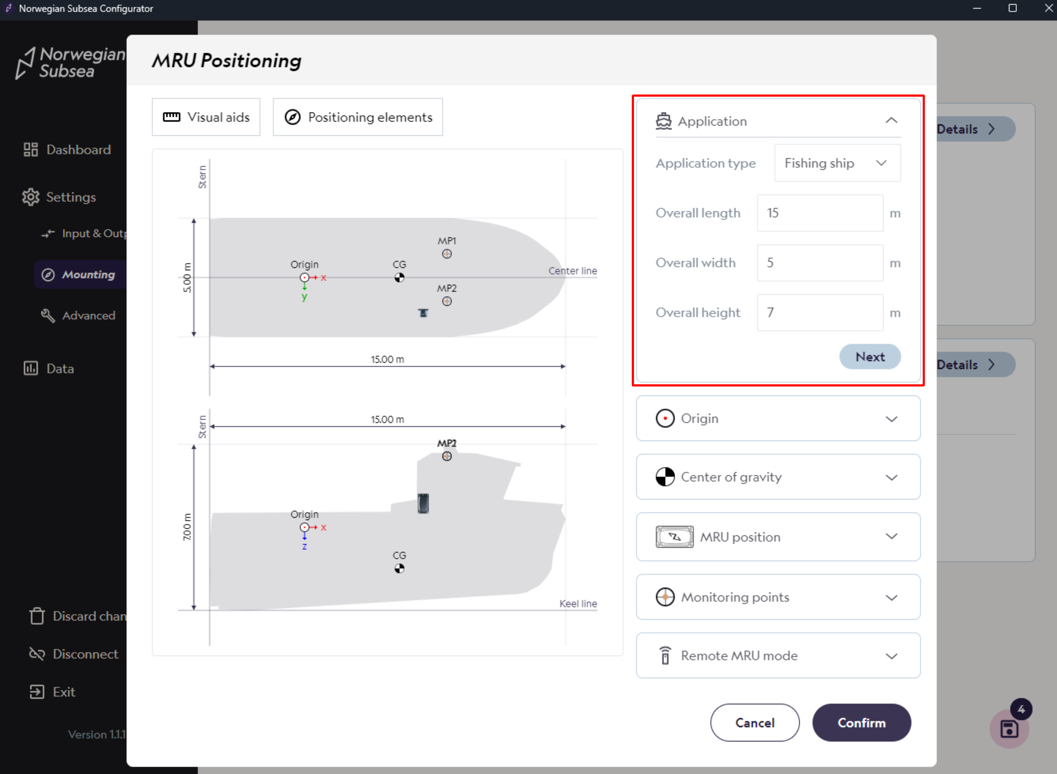
To set the position of the MRU, click “Details“ under the MRU position card.
-
First enter the application type and its dimension and click “Next“
-
Application type: Fishing ship
-
Dimensions:
-
Length: 15 m
-
Width: 5 m
-
Height: 7 m
-
-
-
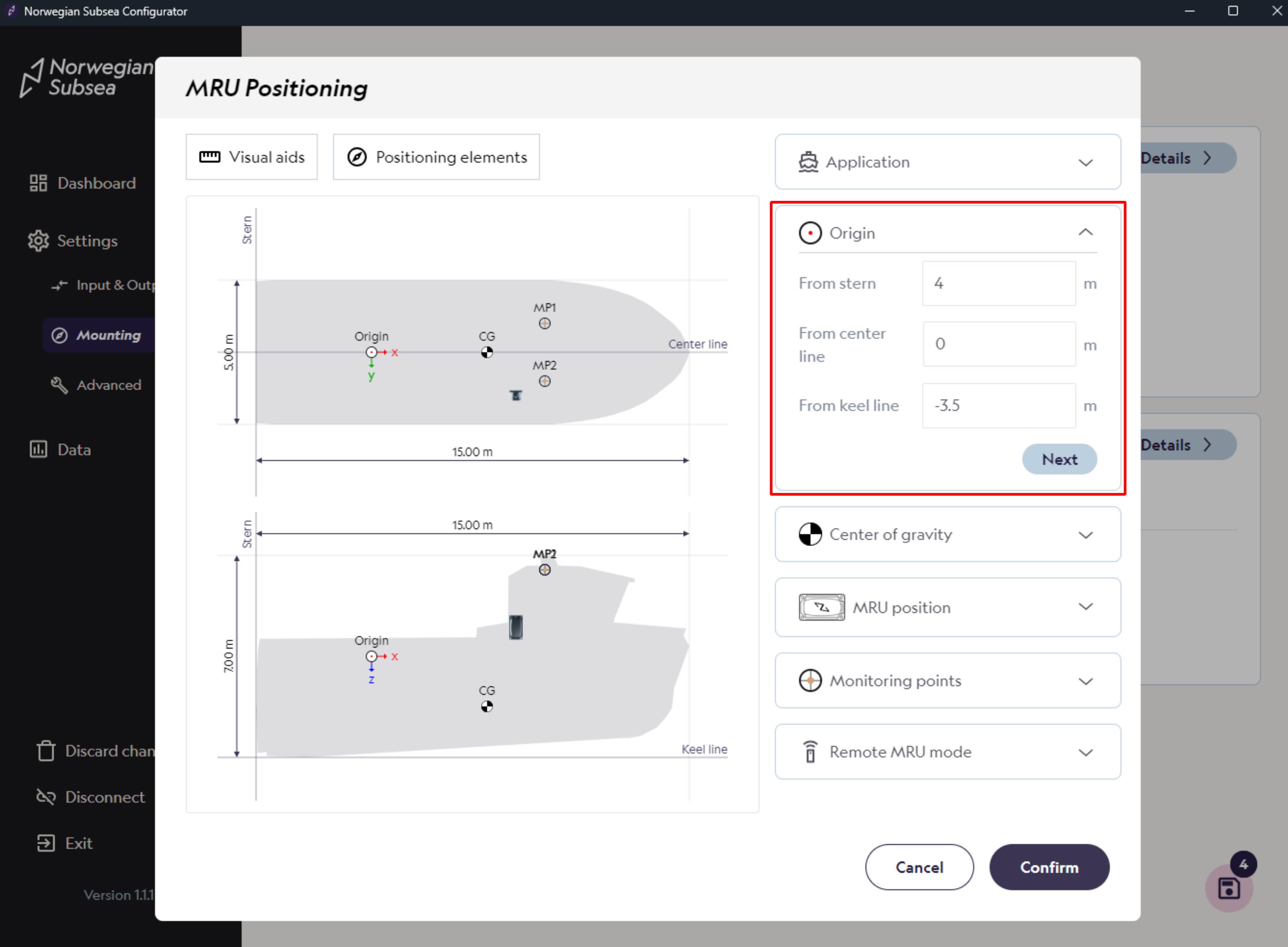
Then enter the survey origin and click “Next“
-
From stern: 4 m
-
From center: 0 m
-
From keel line: -3.5 m
-
-
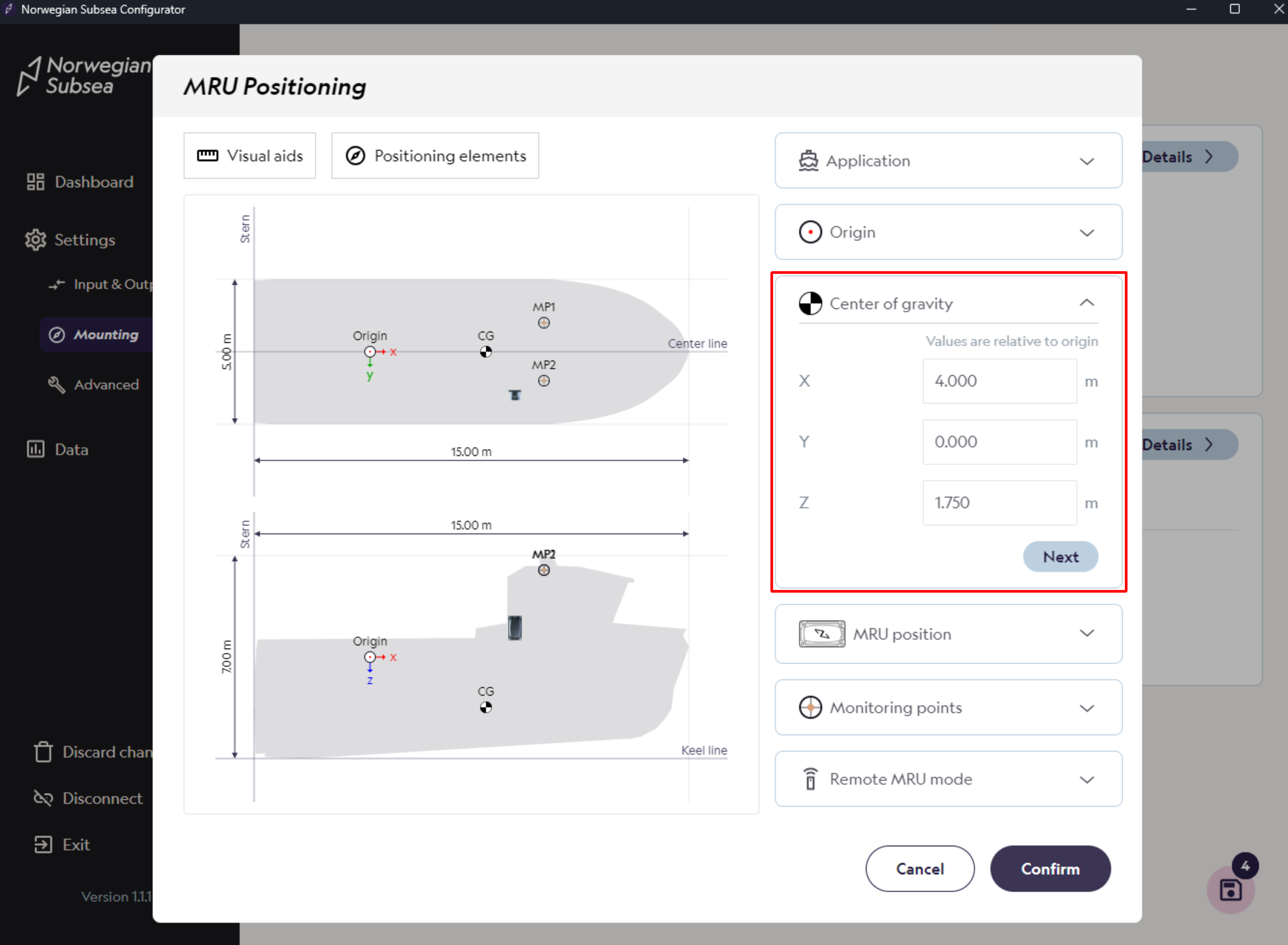
Then enter the center of gravity and click “Next“
-
X: 4 m
-
Y: 0 m
-
Z: 1.75 m
-
-
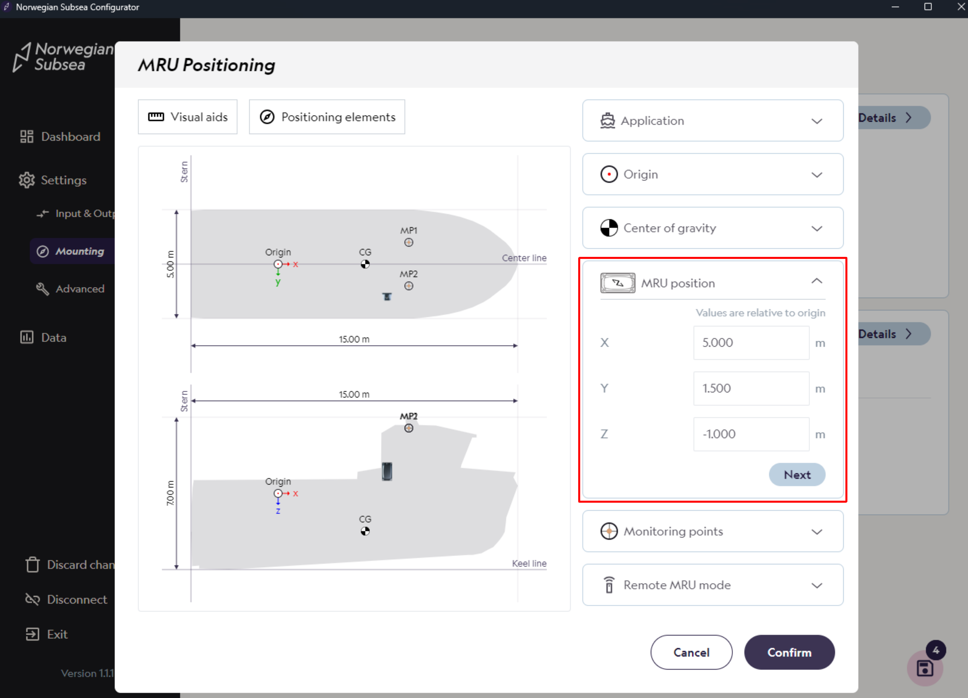
Then enter the MRU position and click “Next“
-
X: 5 m
-
Y: 1.5 m
-
Z: -1 m
-
-
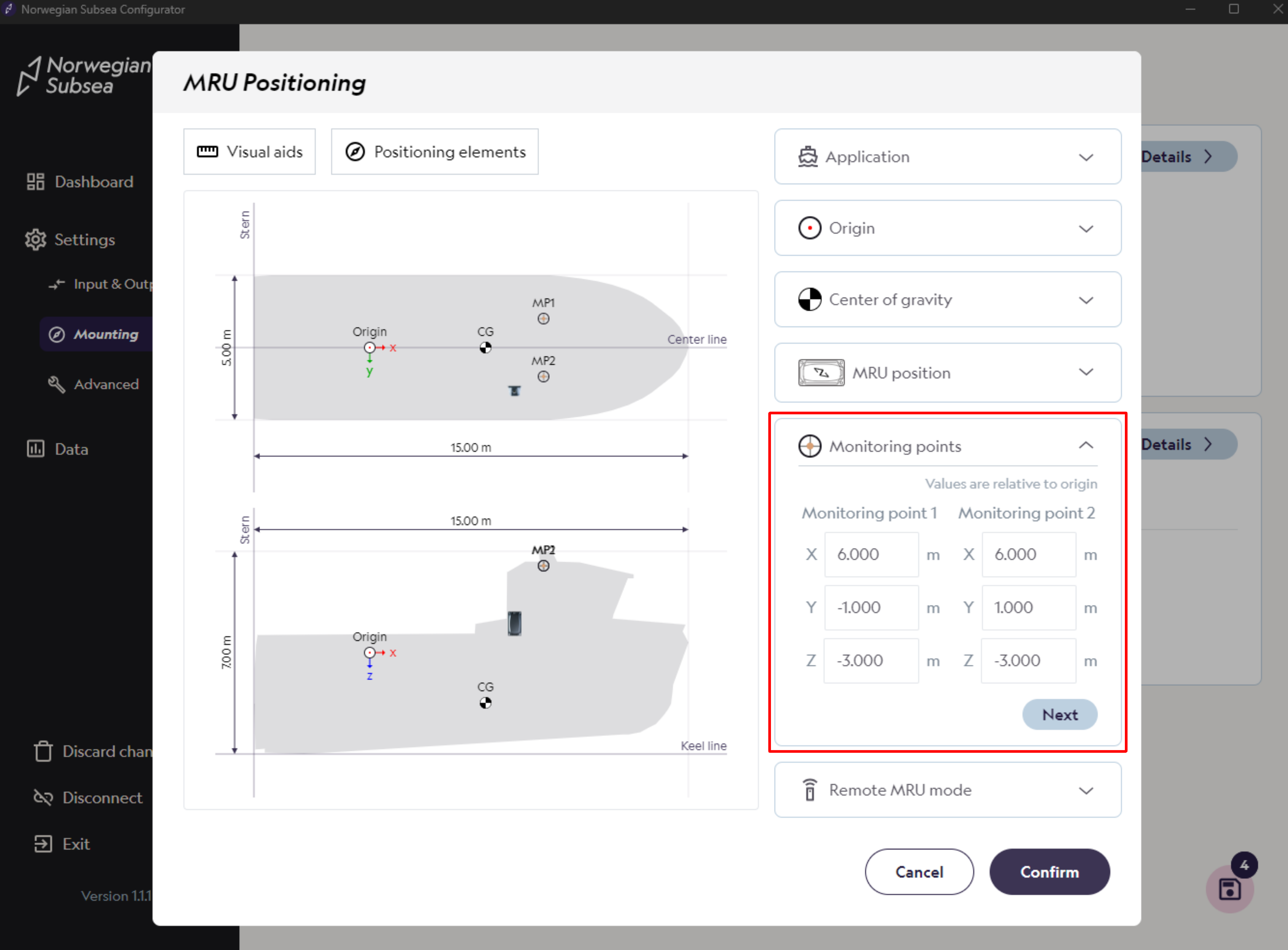
Then enter monitoring points and click “Next“
-
Monitoring point 1
-
X: 6 m
-
Y: -1 m
-
Z: -3 m
-
-
Monitoring point 2
-
X: 6 m
-
Y: 1 m
-
Z: -3 m
-
-
-
Finally, enter remote MRU mode and click “Confirm“
-
Remote MRU mode: Virtual MRU
-
Save changes
Make sure to save your changes, so they also persist after reboot.