
Accuracy in roll and pitch is not a single quantity. The figure on a datasheet states how closely the output follows a known motion. It does not state where the reading sits on a level surface, how long that reading remains valid, or how well it aligns with the vessel axes. These are distinct quantities, and on the same unit they can differ by more than an order of magnitude. This page defines them and states how Norwegian Subsea measures and specifies its figures.
How an MRU determines roll and pitch
An MRU contains gyroscopes, which measure angular rate, and accelerometers, which measure specific force. When the unit is stationary the measured specific force is the reaction supporting it against gravity, and its direction gives the vertical. The gyroscopes measure how the orientation changes, but provide no absolute reference. The accelerometers are the only source of information about which way is down.
Three consequences follow, and they account for most of what is on this page.
The accelerometers determine the result. Over intervals of a few seconds the gyroscopes carry the output, which keeps it smooth and allows short accelerations to be rejected. Over longer intervals the output follows the vertical as measured by the accelerometers. Improved filtering does not change this, because the filter has no other source of absolute reference.
An error in specific force becomes an angular error. With the MRU level, the measured specific force lies almost entirely along the vertical accelerometer axis. If a horizontal accelerometer reads a non-zero value when the true value is zero, the measured vertical tilts by the ratio of the horizontal reading to the vertical one. An error of 1 mg against 1 g tilts it by approximately 0.057 degrees. Holding roll and pitch to 0.01 degrees requires the horizontal accelerometers to be correct to within 175 micro-g, across all operating conditions and after every restart. An error on the vertical axis contributes far less, because it changes the magnitude of the measured vector rather than its direction.
A stationary MRU cannot distinguish tilt from bias. A genuinely tilted unit and a level unit with a horizontal accelerometer bias produce identical measurements, and nothing in the measurement separates them. External aiding, such as GNSS velocity, makes the bias observable once the vessel is moving, but contributes little when it is stationary. This is a property of the measurement problem, not a limitation of a particular sensor or algorithm.
Five quantities, all called accuracy
1. Short-term stability (static accuracy)
The MRU is stationary and the output is logged over a fixed window. The true angle does not change, so any variation in the output is the sensor's own noise and drift.
The test has no external reference. The only assumption is that the true angle is constant. Anything that does not vary during the test is therefore invisible in the result: a constant offset, a scale factor error, a lag. The figure states how quiet the output is, not how correct it is.
It also establishes that the MRU requires no motion in order to converge. Norwegian Subsea MRUs settle and hold their reading with no excitation.
2. Tracking error (dynamic accuracy)
The MRU is mounted on a rotary stage and exposed to a defined motion. The output is compared against the stage angle, and the residual is the tracking error. The MRU is zeroed to the stage before the run, so the figure states how closely the output follows the motion from a known starting point. It includes noise, dynamic response, cross-axis coupling and scale factor error.
This is the figure quoted on the datasheet, and it is what distinguishes the MRU 3000, 6000 and 9000.
Because the stage angle is known, this is a true error measurement. The stationary test is not.
3. Absolute levelling error
An MRU is placed on a perfectly level surface and switched on. The reading may not be zero. Whatever it reads is the absolute levelling error.
The datasheet figure does not describe this, because it is measured from a zero established before the test. Two effects contribute.
Accelerometer bias. Factory calibration removes the bias present at the time of calibration. It cannot remove the bias that is re-established each time the unit is powered on. This is the larger of the two effects, and it is present in every MRU operating without external aiding.
Alignment of the accelerometer axes to the housing. This is measured and corrected during calibration. The residual is limited by the accuracy of the reference for true level on the calibration bench, and is below one hundredth of a degree. It is not a significant contributor.
Manufacturers rarely state this figure in a specification table, Norwegian Subsea included. In a real installation it is not the limiting term, as quantity 5 sets out. Where a figure of this kind does appear on a datasheet, it may not be labelled as such.
4. Zero stability
A zero does not remain valid indefinitely. Two effects degrade it.
Time and temperature. The MRU is temperature calibrated across its full operating range, so a change in temperature moves the zero very little. What remains is slow drift.
Power cycling. A restart re-establishes the accelerometer bias, and the reading can shift immediately. The shift is not gradual and is not visible in the data: the output is as steady after the restart as it was before. Measured across many restarts, the spread of that shift is the restart repeatability, which is the same bias effect expressed differently.
5. Installed accuracy in the vessel frame
In most applications the quantity of interest is the roll and pitch of the vessel, not the orientation of the MRU housing. The MRU is one link in that chain, and the remaining links are normally larger than any of the sensor terms above:
-
the MRU base against its mounting bracket
-
the bracket against the hull structure, including weld distortion and plate flatness
-
the trim and heel of the vessel at the time of installation
-
the definition of the vessel frame itself
The last of these is not a mechanical problem. Whether the x axis runs from the midpoint of the stern to the midpoint of the bow, whether the hull is symmetric, and whether a given bulkhead is square to the keel are questions without a single correct answer. Part of this error is therefore definitional and cannot be removed by measurement.
Installation error in roll and pitch is a constant offset. It moves where zero sits. It does not make the output noisier or slower. Short-term stability and tracking error are unchanged by the quality of the installation.
Because it is a constant offset, it is removed in the configuration software, in two stages. The main rotation angles set the coarse orientation of the MRU axes relative to the vessel axes in 90 degree steps, matching how the unit is physically mounted. The offset angles then correct the remainder, with the resulting output displayed next to each field.
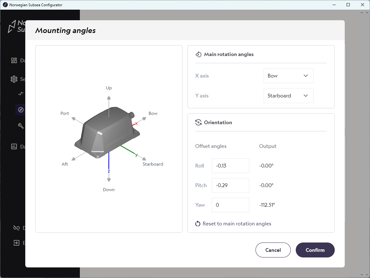
Two approaches are in common use.
Zeroing in a known condition. The offset angles are adjusted until the output reads zero with the vessel in a known condition, typically flat calm water at a known loading. All subsequent measurements are relative to that condition. This is sufficient for most applications.
Matching an existing reference. The offset angles are adjusted until the MRU agrees with another reference on the vessel, such as an inclinometer or the trim and heel reported by the loading computer. The MRU then reads consistently with the rest of the bridge. The result inherits the accuracy of that reference.
Once the main rotation angles are set, the remaining fine offset is small. Its effect on the tracking figure scales with the cosine of that offset and amounts to well under a thousandth of a degree.
Yaw misalignment is not an offset
A yaw error does not behave as a roll or pitch error does. It rotates the roll and pitch axes within the horizontal plane, so roll couples into pitch and pitch into roll. Measured roll becomes the true roll scaled by the cosine of the yaw error, plus the true pitch scaled by its sine.
The coupling is zero when the vessel is level and increases with the motion amplitude. Zeroing does not remove it, because zeroing removes constant offsets and this is not one. A unit zeroed correctly in flat calm water will still show the error once the vessel begins to move. A yaw error of 1 degree with a pitch amplitude of 2 degrees introduces 0.035 degrees into roll, which already exceeds the MRU 9000 specification.
Gravity carries no information about yaw, so this error cannot be determined from a stationary measurement. It must be handled either by surveying the mounting against the vessel axes, or by a dynamic calibration in a seaway. The cross-axis coupling internal to the MRU is a separate matter, and is measured and corrected at the factory.
How Norwegian Subsea specifies roll and pitch accuracy
Specified tracking error:
|
Model |
Roll and pitch |
|---|---|
|
MRU 3000 |
0.05 degrees |
|
MRU 6000 |
0.02 degrees |
|
MRU 9000 |
0.01 degrees |
Test conditions for both published quantities:
|
Condition |
Short-term stability (static accuracy) |
Tracking error (dynamic accuracy) |
|---|---|---|
|
Excitation |
Stationary |
Regular sinusoidal roll and pitch |
|
Amplitude |
Not applicable |
Plus/minus 5 degrees |
|
Period |
Not applicable |
10 s |
|
Window |
30 min |
Typically 5 to 10 min |
|
Statistic |
RMS |
RMS |
|
Reference |
None. True angle is constant. |
Rotary stage |
|
Zeroing |
Aligned to reference before test |
Zeroed to stage before run |
In both tests the MRU is zeroed to the reference before the run, so the mean is already removed and the RMS and 1 sigma figures coincide.
Both quantities are measured on every unit during validation and are recorded on the validation certificate.
The specified figure applies both to the unit standing still and to the unit in motion. Measured short-term stability is typically at or below the specified tracking error, so the stationary case is not the limiting one. A separate and lower static figure is therefore not quoted.
How to read an accuracy figure
A figure is only interpretable alongside the conditions under which it was measured, and the same number can describe different quantities. The following should be established, whether reading a Norwegian Subsea specification or another manufacturer's.
Was the mean removed? Almost every published figure is measured from a zero established before the test, either by aligning the unit to the reference or by subtracting the residual mean afterwards. This makes it a precision figure. It states nothing about where the reading sits on a level surface.
Was there a reference? A stationary test has no reference angle, so it measures variation rather than error. A test against a rotary stage or motion table measures error against known truth. Neither quantity contains the other.
What motion was applied? A single-frequency sinusoid at small amplitude is a considerably more favourable test than irregular motion in real sea conditions. Amplitude, period and duration should all be stated.
Over what duration? The result of a stationary test depends on the length of the window, because noise averages down while drift accumulates.
Was aiding required? Some published figures require external GNSS or RTK and do not apply to an unaided installation. As above, aiding improves performance once the vessel is moving and contributes little when it is stationary.
RMS or 1 sigma? The two terms are used interchangeably across MRU datasheets. They coincide once the mean has been removed, which it almost always has.
Summary
|
Quantity |
Reference |
Mean removed |
What it states |
|---|---|---|---|
|
Short-term stability (static accuracy) |
None |
Yes |
How quiet and steady the output is |
|
Tracking error (dynamic accuracy) |
Rotary stage |
Yes |
How closely the output follows a known motion |
|
Absolute levelling error |
Gravity |
No |
Where the reading sits on a level surface |
|
Zero stability |
Gravity |
No |
How long a zero remains valid |
|
Installed accuracy |
Vessel frame |
No |
The roll and pitch of the vessel itself |
The first two are stated in the specification table. The remainder are rarely stated by manufacturers, and are set out here so that they can be distinguished.
For guidance on which quantity applies to a given application, contact support@norwegian-subsea.no.