Ethernet cables (RJ50) are available in two versions - normal (terminated with connectors at both ends) and pigtail (connector on one end only) - and can be supplied in various lengths.
Normal
Cable assembly overview
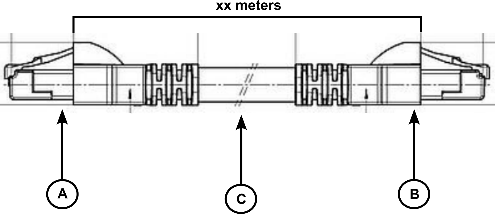
For Ethernet cables with RJ50 connectors at both ends, the assembly consists of three parts:
-
Connector A: RJ50 plug, 10-pin male. Connects to the MRU.
-
Connector B: RJ50 plug, 10-pin male. Connects to the system output.
-
Cable (C): Round stranded Cat5e/6 cable or 10-conductor stranded round cable.
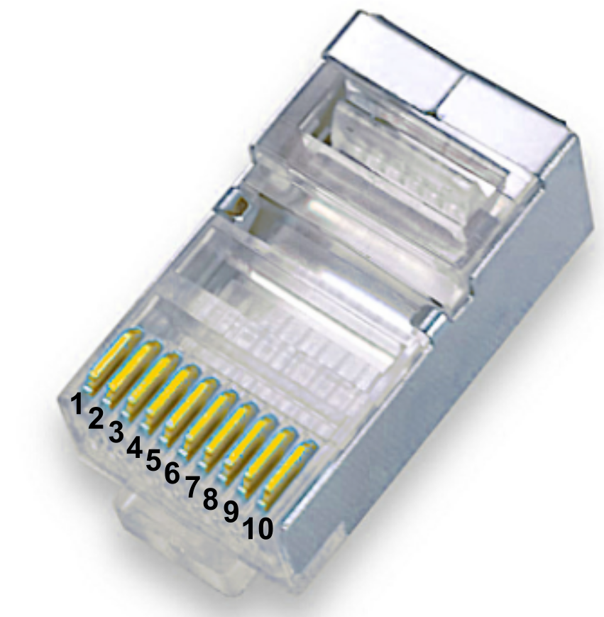
RJ50 connector view
Overview of the male RJ50 connector, including pin number.
Pinout diagram
Pinout diagram specifying the cable assembly from connector A to connector B, including pin number, wire color, and gauge/pair connections.
|
ETHERNET NORMAL CABLE ASSEMBLY PINOUT DIAGRAM (RJ50) |
|||
|---|---|---|---|
|
PIN (connector A) |
COLOR |
PAIR |
PIN (connector B) |
|
1 |
Black |
Pair 1 |
1 |
|
2 |
Grey |
Pair 2 |
2 |
|
3 |
White |
Pair 2 |
3 |
|
4 |
Red |
Pair 3 |
4 |
|
5 |
Orange |
Pair 3 |
5 |
|
6 |
Blue |
Pair 4 |
6 |
|
7 |
Purple |
Pair 4 |
7 |
|
8 |
Yellow |
Pair 5 |
8 |
|
9 |
Green |
Pair 5 |
9 |
|
10 |
Brown |
Pair 1 |
10 |
Pigtail
Cable assembly overview
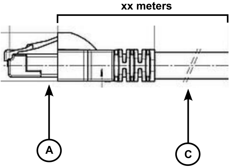
For Ethernet cables with RJ50 connectors on one end only, the assembly consists of two parts:
-
Connector A: RJ50 plug, 10-pin male. Connects to the MRU.
-
Cable (C): Round stranded Cat5e/6 cable or 10-conductor stranded round cable.
RJ50 connector view
Overview of the male RJ50 connector, including pin number.
Pinout diagram
Pinout diagram specifying the pigtail cable assembly, including pin number, wire color, and gauge/pair connections.
|
ETHERNET PIGTAIL CABLE ASSEMBLY PINOUT DIAGRAM (RJ50) |
||
|---|---|---|
|
PIN (connector A) |
COLOR |
PAIR |
|
1 |
Black |
Pair 1 |
|
2 |
Grey |
Pair 2 |
|
3 |
White |
Pair 2 |
|
4 |
Red |
Pair 3 |
|
5 |
Orange |
Pair 3 |
|
6 |
Blue |
Pair 4 |
|
7 |
Purple |
Pair 4 |
|
8 |
Yellow |
Pair 5 |
|
9 |
Green |
Pair 5 |
|
10 |
Brown |
Pair 1 |
MRU signal diagram
To find the associated MRU signal diagram, check out section “MRU Compact RJ50 signal diagram” here .