Quick start guide
This tutorial will guide you through the first connection of your MRU unit. It will first provide instructions on where to find and download our software tools and walk you through the steps to successfully complete your first connection with your MRU.
Overview
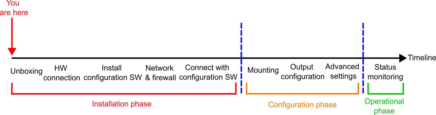
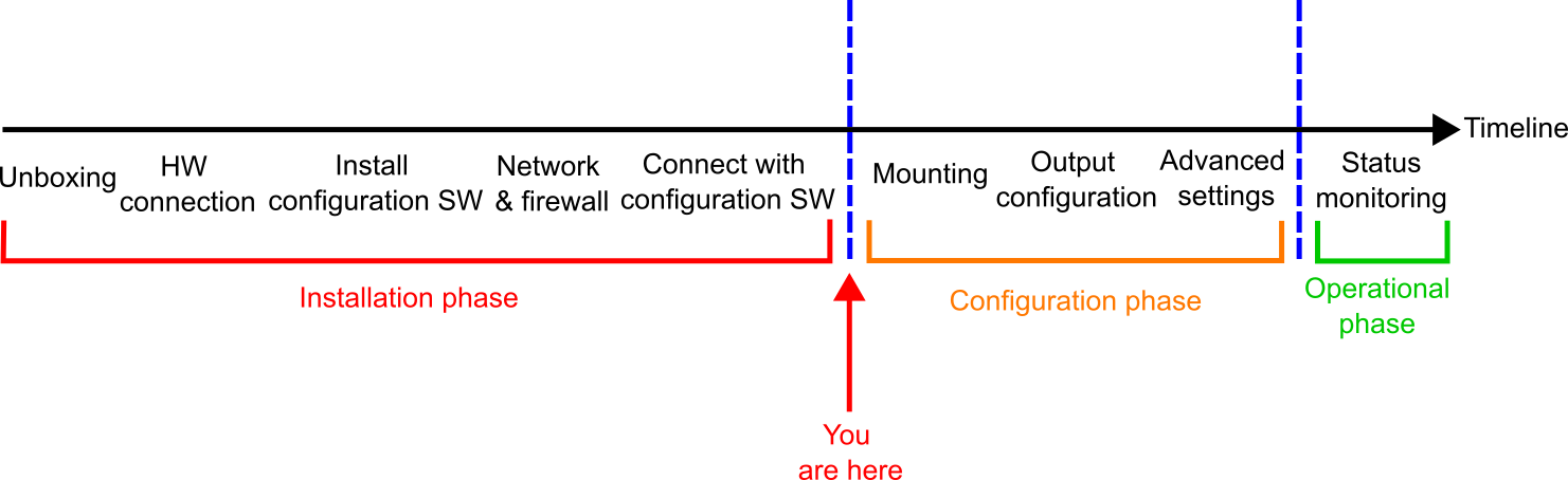
A step-by-step overview of the setup process, organized into three phases:
Installation phase – Covers everything from unboxing to establishing your first connection with the MRU.
Configuration phase – Once connected to the MRU via the configuration software, proceed with the physical installation and set mounting parameters, output formats, and other advanced settings.
Operational phase – After configuration, monitor the MRU’s status and other relevant parameters during regular operation.
Unboxing
First, unbox your MRU. For more information about the different MRU types, cables, junction boxes and other accessories, see here.
Hardware connection
After unboxing, connect the accessories to the MRU. The following examples show how this can be done for both the MRU Marine and the MRU Compact.
MRU Marine
Hardware connection list with MRU Marine:
1 x MRU Marine
1 x Standard marine cable
1 x Junction box 2.0
1 x Power cable and power supply (9-36 V)
1 x Ethernet cable
1 x Host PC
The system set-up is summarized in the following steps:
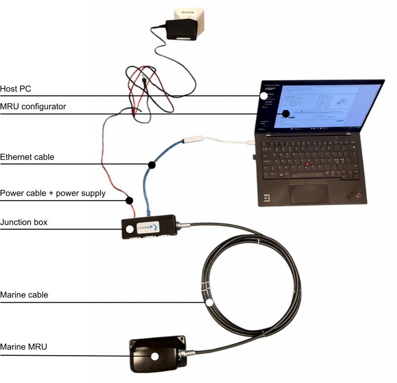
1. Connect the female connector of the MRU marine cable to the MRU socket, and its male connector to the round socket on the junction box.
2. Connect the junction box to the host PC via Ethernet or serial (RS-232/RS-485) using the dedicated port.
3. Connect the power supply to the power port on the junction box. It is recommended to plug the power supply into the power socket last, as this action will power up both the junction box and the MRU.
The image below shows how to connect the accessories to the MRU Marine.
MRU Compact
Hardware connection list with MRU Compact:
1 x MRU Compact
1 x PoE splitter
1 x Power cable and power supply (9-36 V)
2 x Ethernet cables
1 x Host PC
The system set-up is summarized in the following steps:
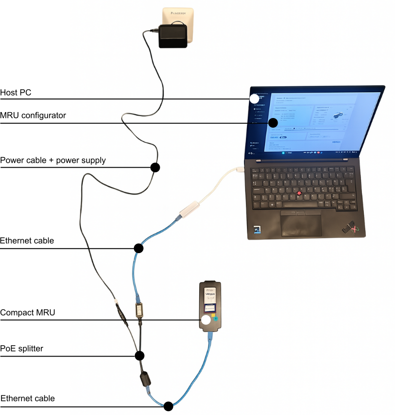
1. Connect the first Ethernet cable to the MRU socket and the Ethernet input (RJ45) on the PoE splitter. This cable carries both power and data.
2. Connect the second Ethernet cable between the host PC and the Ethernet output (RJ45) on the PoE splitter. This cable carries data only.
3. Connect the power supply to the power port on the PoE splitter, and plug the power supply into a power socket.
The image below shows how to connect the accessories to the MRU Compact.
For more information about mechanical and eletrical interfaces for the MRUs, see here.
Serial communication
While the overview above covers two typical demo setups for the MRU, other common communication options - such as serial communication (RS-232/RS-485) - are also widely used.
MRU Subsea setup
The setup of the MRU Subsea is similar to that of the MRU Marine and Compact but is delivered with a subsea cable featuring an 8-pin SubConn connector.
Install MRU configurator
You will need to install our software tool on your PC to establish connection and configure your MRU unit. The MRU configurator can be installed here.
Network and firewall
After connecting the hardware, configure the network so that the MRU is reachable through your Ethernet interface. You can follow the procedure described here.
If you are still unable to establish a connection to the MRU, you may need to manually add an exception for the configuration software in the Windows Firewall settings. For more information, see here.
Connect with MRU configurator
Connect to your MRU using the MRU Configurator:
1. Open the application (on your host PC)
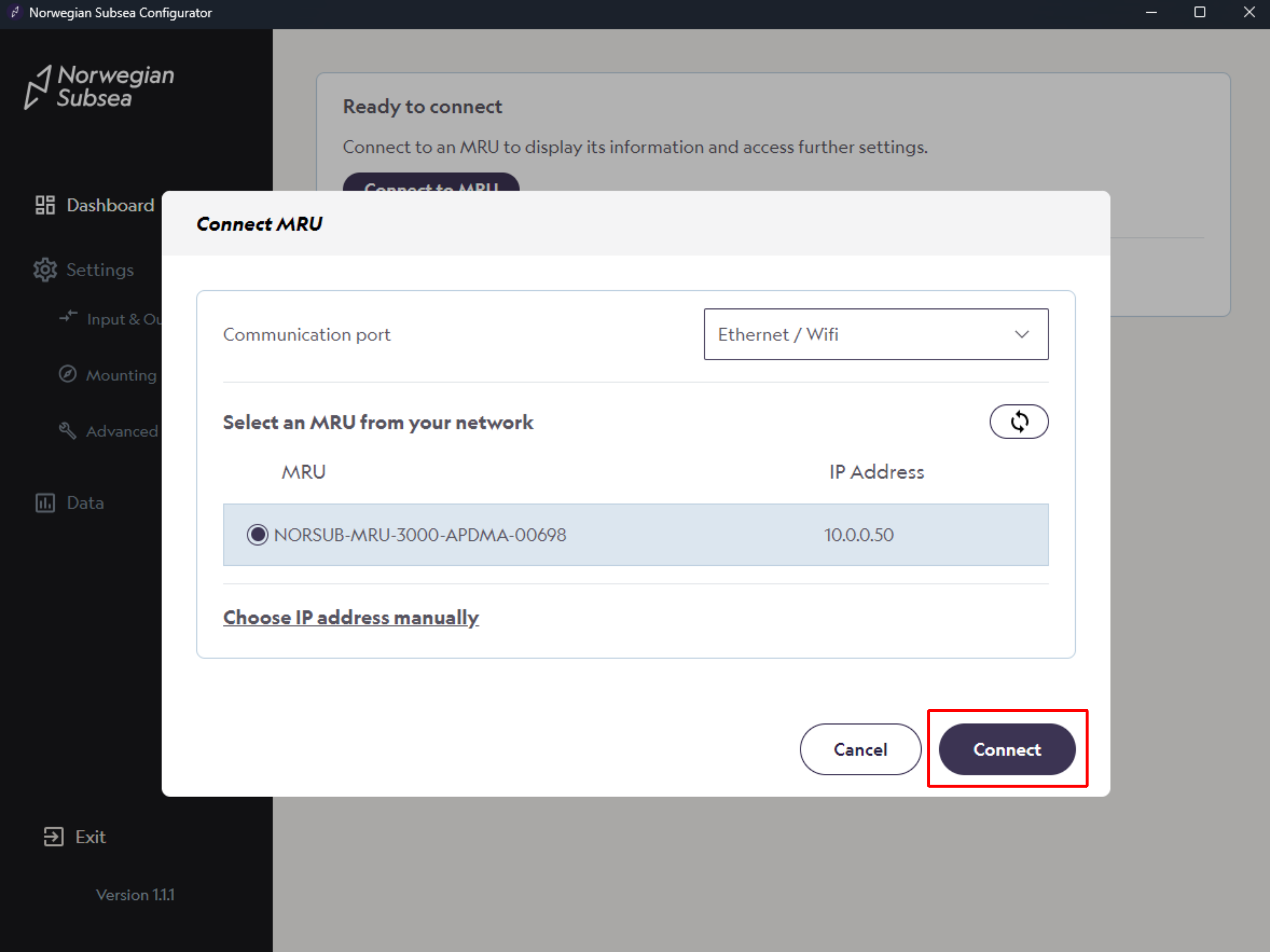
2. Click “Connect to MRU“
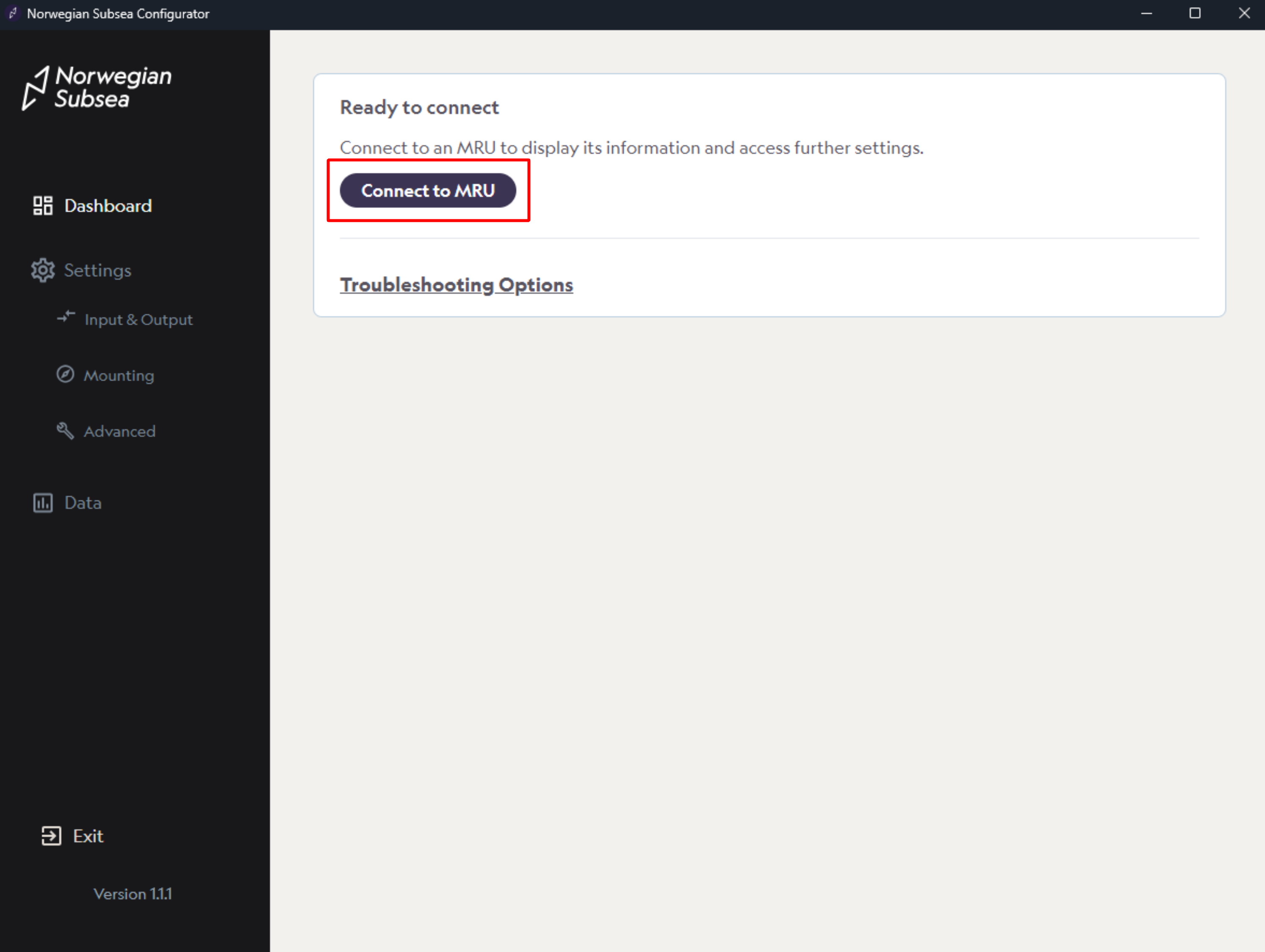
3. Select the MRU unit automatically detected from the list. Alternatively, enter the IP address manually. Then click “Connect“.
4. Configure your MRU with the desired settings. A default factory setup is preconfigured.
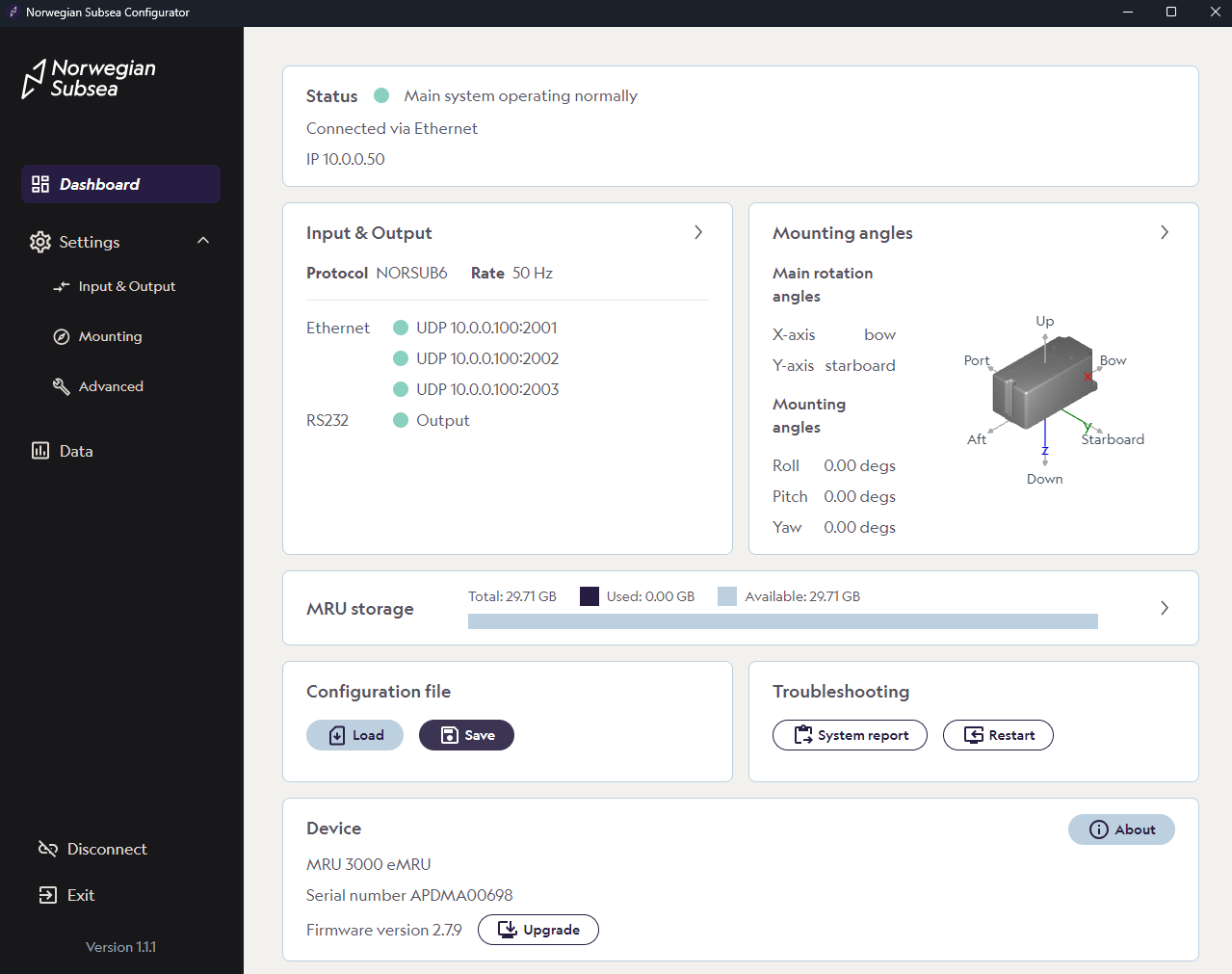
We advise you to follow the configuration handbook to configure the device according to your specific requirements, including mounting, output configuration and other advanced settings.
Firmware updates
If you need to upgrade the MRU, see here.
Documentation and resources
You can find more information about the MRU in the support portal, or by downloading product manuals and other documents here. If you need more help, reach out to support@norwegian-subsea.no.