This tutorial explains how to setup PPS synchronization with the MRU Marine or MRU Compact. It covers the following steps:
-
Pinout overview: Displays the pinout diagrams for each MRU Marine and MRU compact.
-
Connect GPS to MRU: Instructions for connecting the GPS to the MRU.
-
Configure MRU and verify PPS: How to configure the MRU and verify PPS synchronization using the MRU configurator.
MRU pinout overview
Overview of the pinout diagrams for MRU Marine and MRU Compact.
MRU Marine signal diagram
|
MARINE 16 PINS CONNECTOR |
||
|---|---|---|
|
PIN NUMBER |
SIGNAL (from MRU, male/female connector) |
CATEGORY |
|
1 |
24V |
POWER |
|
2 |
GND |
|
|
3 |
Tx_D1+ |
ETHERNET |
|
4 |
Tx_D1- |
|
|
5 |
Rx_D2+ |
|
|
6 |
Rx_D2- |
|
|
7 |
Tx+ (RS-485) |
RS-485 |
|
8 |
Tx- (RS-485) |
|
|
9 |
Rx+ (RS-485) |
|
|
10 |
Rx- (RS-485) |
|
|
11 |
Tx (RS-232) |
RS-232 |
|
12 |
Rx (RS-232) |
|
|
13 |
sync1 (PPS) |
SYNC |
|
14 |
Tx (RS-232) GPS |
AIDING |
|
15 |
Rx (RS-232) GPS |
|
|
16 |
Shield |
SHIELD |
For more information about the electrical interface of the MRU Marine, see here.
MRU Compact RJ50 signal diagram
|
RJ50 PINOUT DIAGRAM |
|
|---|---|
|
PIN NUMBER |
SIGNAL (from MRU, female connector) |
|
1 |
VCC (9-36V) |
|
2 |
SYNC2 |
|
3 |
SYNC1 (PPS) |
|
4 |
Rx_D2+ |
|
5 |
Rx_D2- |
|
6 |
RX (RS232 GPS) |
|
7 |
TX (RS232 GPS) |
|
8 |
Tx_D1+ |
|
9 |
Tx_D1- |
|
10 |
GND |
For more information about the electrical interface of the MRU Compact, see here.
Connect GPS to the MRU
To connect the GPS to the MRU, do the following:
-
1. Connect the PPS signal from the GPS to the signal Sync1 (PPS)
-
2. Connect the RS232 Tx signal from the GPS to the signal RX (RS232 GPS)
-
3. Connect the RS232 GND signal from the GPS to the signal GND
Configure MRU and verify PPS
Configure MRU for PPS
-
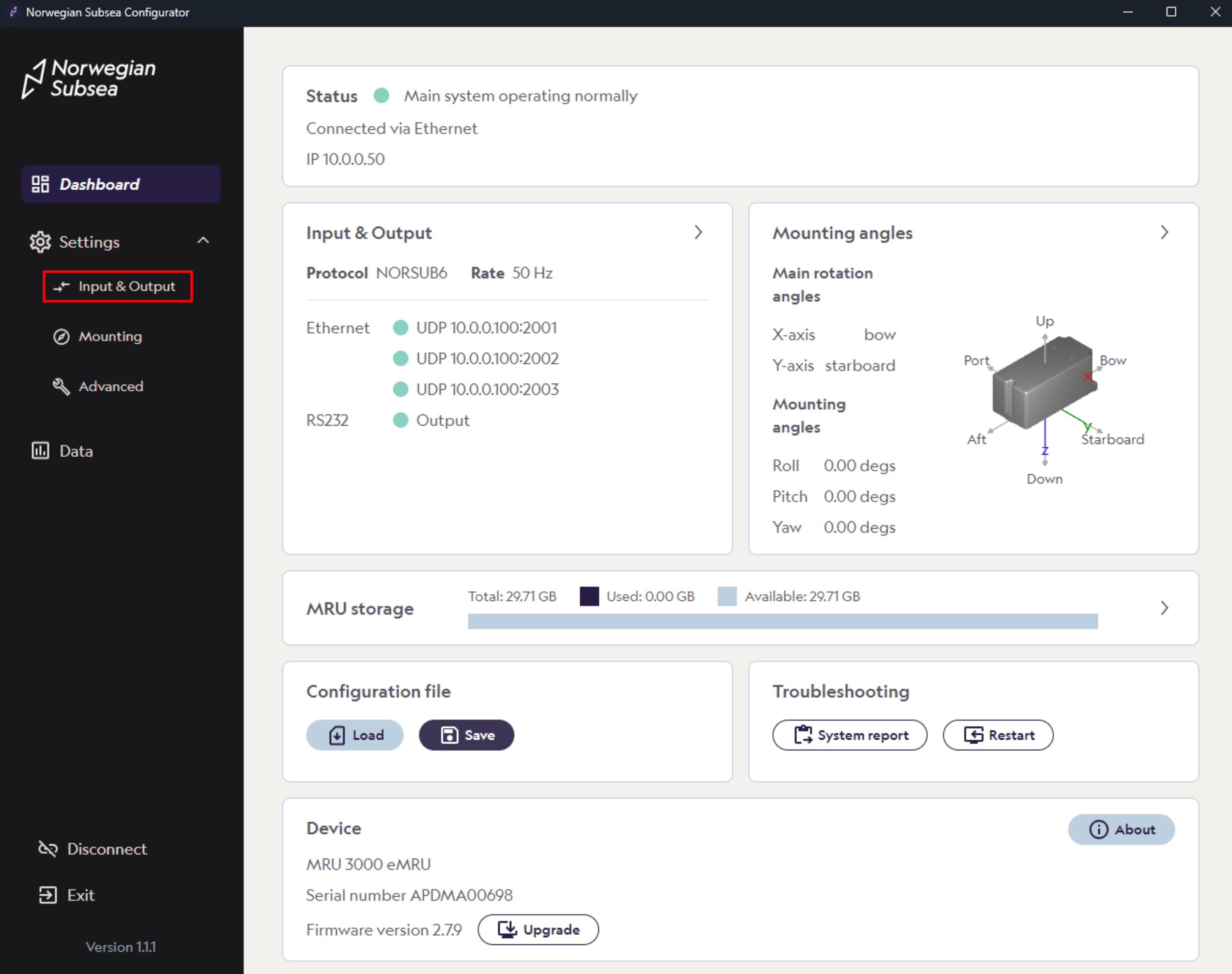
Open the MRU configurator and connect to your MRU.
-
Click “Settings“ -> “Input & Output“ in the left bar
-
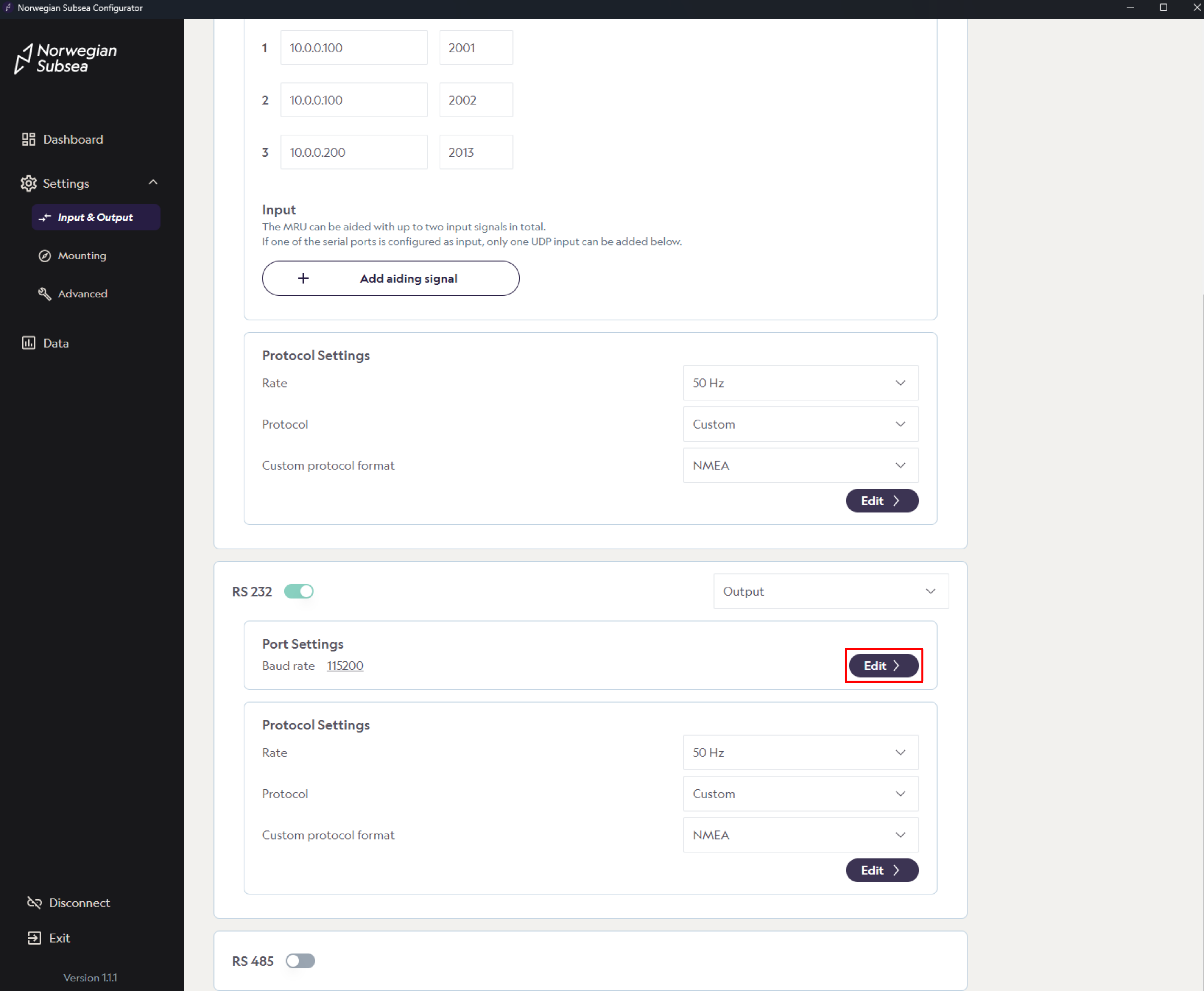
Under the RS 232 section, find port settings and click “Edit“
-
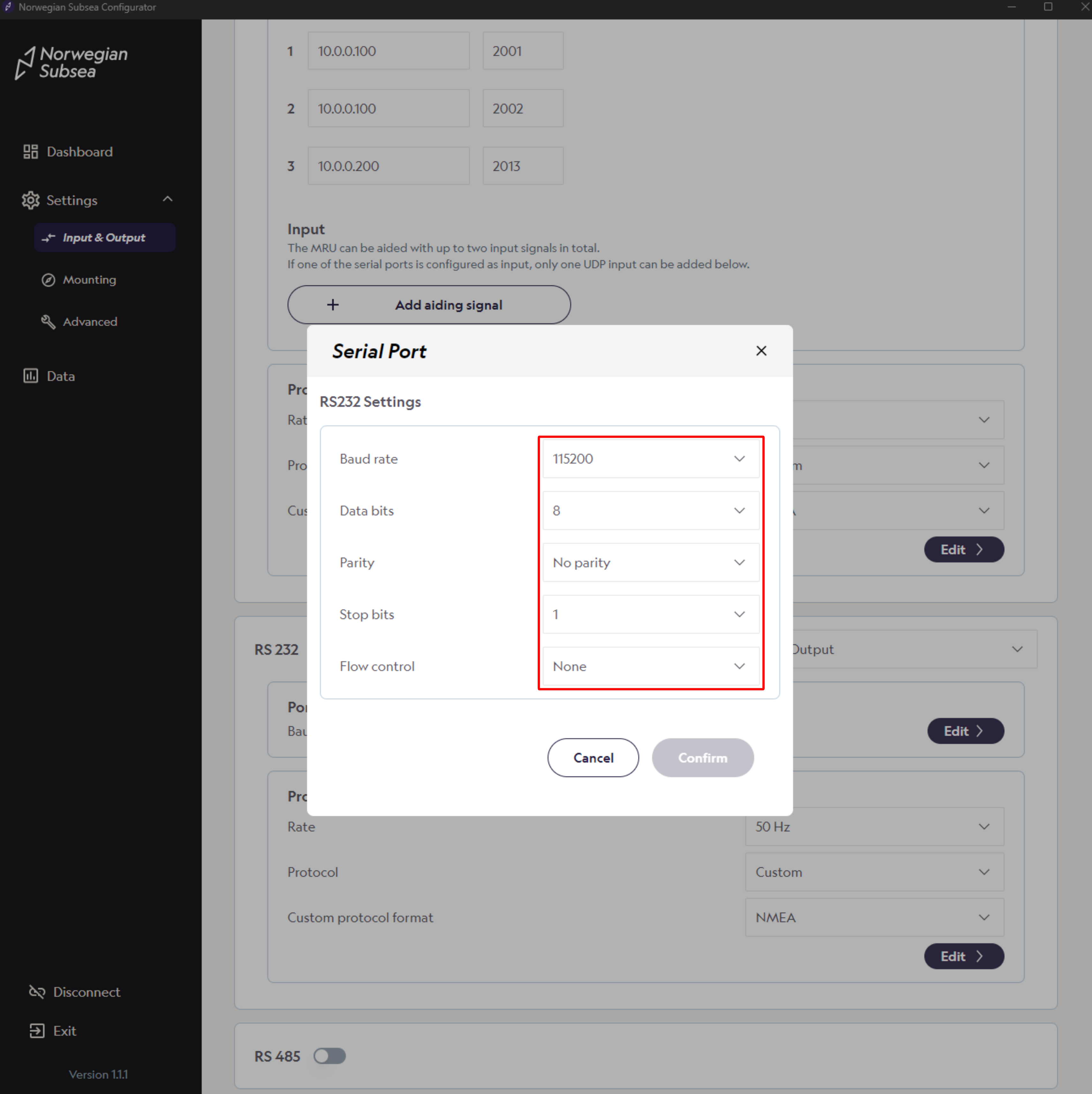
Verify that UART from GPS (RS-232 port settings) is correctly configured. Default values should be used:
-
Baudrate: 115200
-
Data bits: 8
-
Parity: No parity
-
Stop bits: 1
-
Flow Control: None
-
-
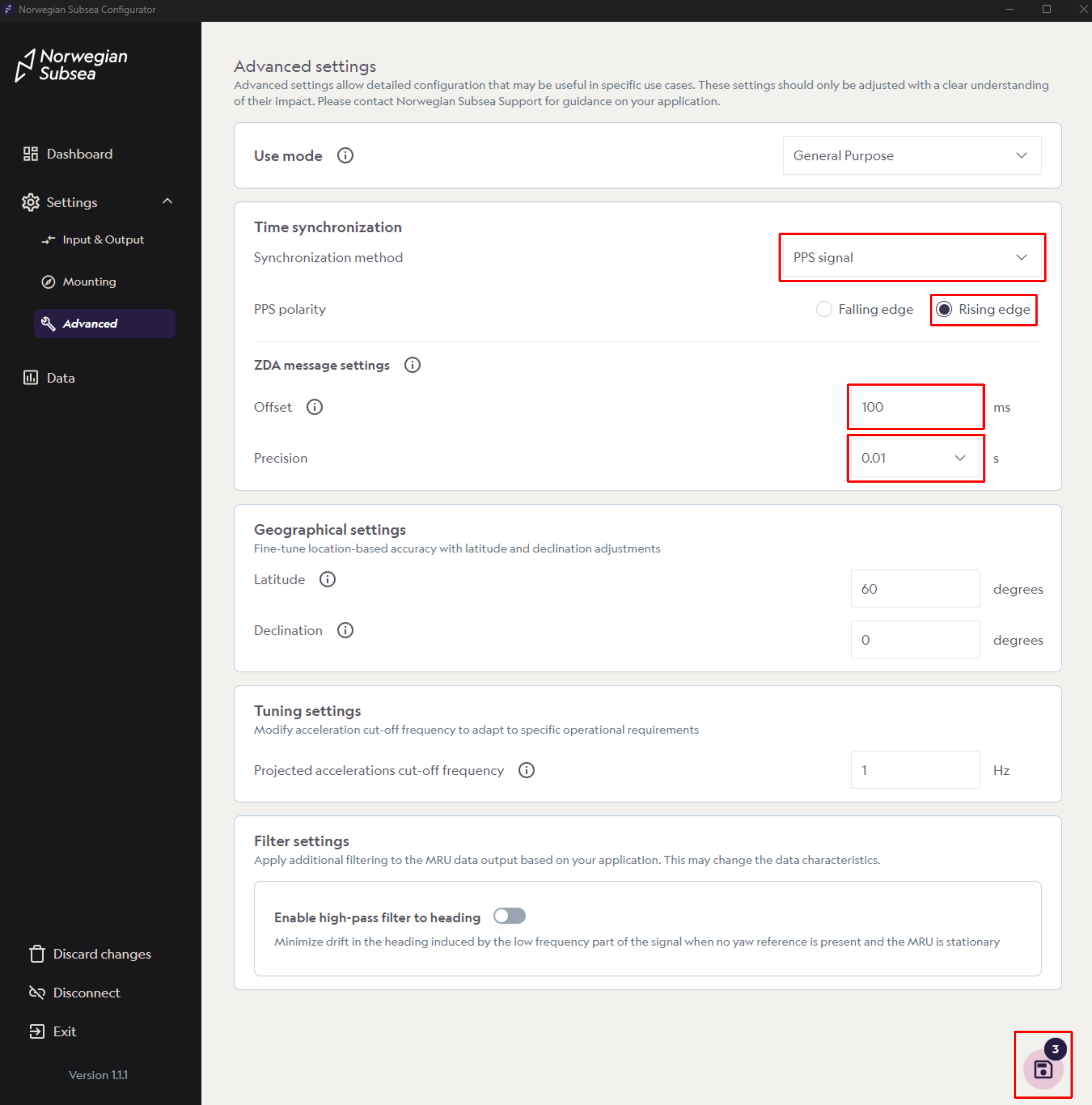
Select PPS signal as synchronization method
-
Choose either Falling edge or Rising edge as PPS polarity
-
Choose Offset (e.g., 100 ms) and Precision (e.g., 0.01 s)
-
Click “Save“
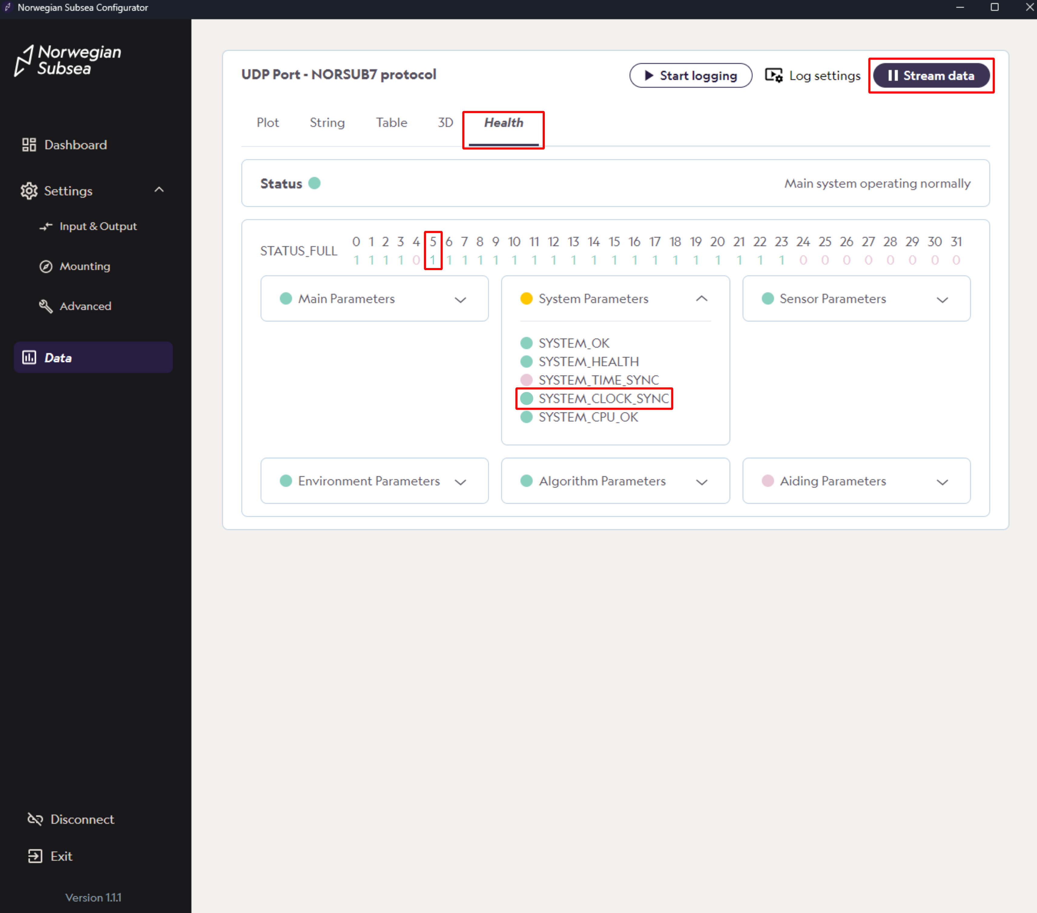
Verify PPS synchronization
To verify PPS synchronization, do the following:
-
Click “Data“ in the left bar
-
In the data section, click “Stream data“
-
Click on the Health section
-
If a valid PPS signal is received, status bit number 5 (SYSTEM_CLOCK_SYNC) is 1 (green).
-
Note: If the PPS signal and at least one ZDA message is not received by the MRU, the SYSTEM_CLOCK_SYNC will be 0 (red).
-
Output protocol with status bits
To view the health status, you need to select an output protocol with MRU status bits included (e.g., NORSUB7). For more details, see here.
Select PPS synchronized timestamp
When PPS is enabled and functioning correctly, the epoch timestamps are synchronized with the reference GPS time and PPS pulse. For example, the posix timestamp output (output variable 506) is synchronized to the GPS time. Note that you can also output the variables TimeLastPPS (output variable 517) and NoLostPPS (output variable 518), which are the milliseconds since the last valid PPS pulse and the number of PPS pulses lost since synchronization with the ZDA message for absolute time. There is also a PPS variable (output variable 516) that goes from 0 to 1 if the GPS and PPS signal is correctly connected and read by the MRU. An overview of the PPS-related output variables can be seen below.
|
PPS-RELATED OUTPUT VARIABLES |
||||
|---|---|---|---|---|
|
NO. |
NAME |
UNIT |
PRECISION |
DESCRIPTION |
|
506 |
PosixTimestamps |
[s] |
Double |
Parser data timestamp in seconds since 12:00 a.m., January 1, 1970, UTC. |
|
516 |
PPS |
[-] |
U8 |
PPS time sync activated. |
|
517 |
TimeLastPPS |
[ms] |
U32 |
Time in ms since last PPS pulse. |
|
518 |
NoLostPPS |
[-] |
U32 |
No lost PPS pulses since last ZDA message received. |