The electrical interface for the MRU Marine and MRU Marine S provides a complete overview of the connectivity options available for these models. It includes male/female connector views and descriptions of the different connector configurations.
MRU Marine
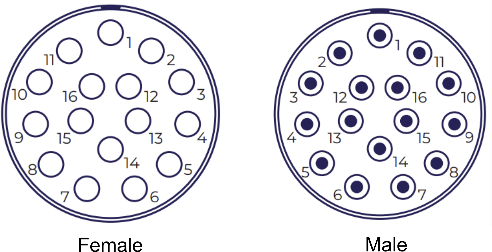
The MRU Marine models are connected to the junction box with a Norwegian Subsea marine cable plugged to a 16 pins marine connector. It comes in a single configuration: a standard 16-pin connector, available in both male and female versions. Note that the male and female versions have identical internal pinout arrangement.
Marine connector view
Overview of female and male 16-pin connectors, both supported for the MRU Marine.
MRU Marine signal diagram
MRU signal diagram for the marine 16 pins connector, showing pin number and associated MRU signals (including its category).
|
MARINE 16 PINS CONNECTOR |
||
|---|---|---|
|
PIN NUMBER |
SIGNAL (from MRU, male/female connector) |
CATEGORY |
|
1 |
24V |
POWER |
|
2 |
GND |
|
|
3 |
Tx_D1+ |
ETHERNET |
|
4 |
Tx_D1- |
|
|
5 |
Rx_D2+ |
|
|
6 |
Rx_D2- |
|
|
7 |
Tx+ (RS-485) |
RS-485 |
|
8 |
Tx- (RS-485) |
|
|
9 |
Rx+ (RS-485) |
|
|
10 |
Rx- (RS-485) |
|
|
11 |
Tx (RS-232) |
RS-232 |
|
12 |
Rx (RS-232) |
|
|
13 |
sync1 (PPS) |
SYNC |
|
14 |
Tx (RS-232) GPS |
AIDING |
|
15 |
Rx (RS-232) GPS |
|
|
16 |
Shield |
SHIELD |
MRU Marine S
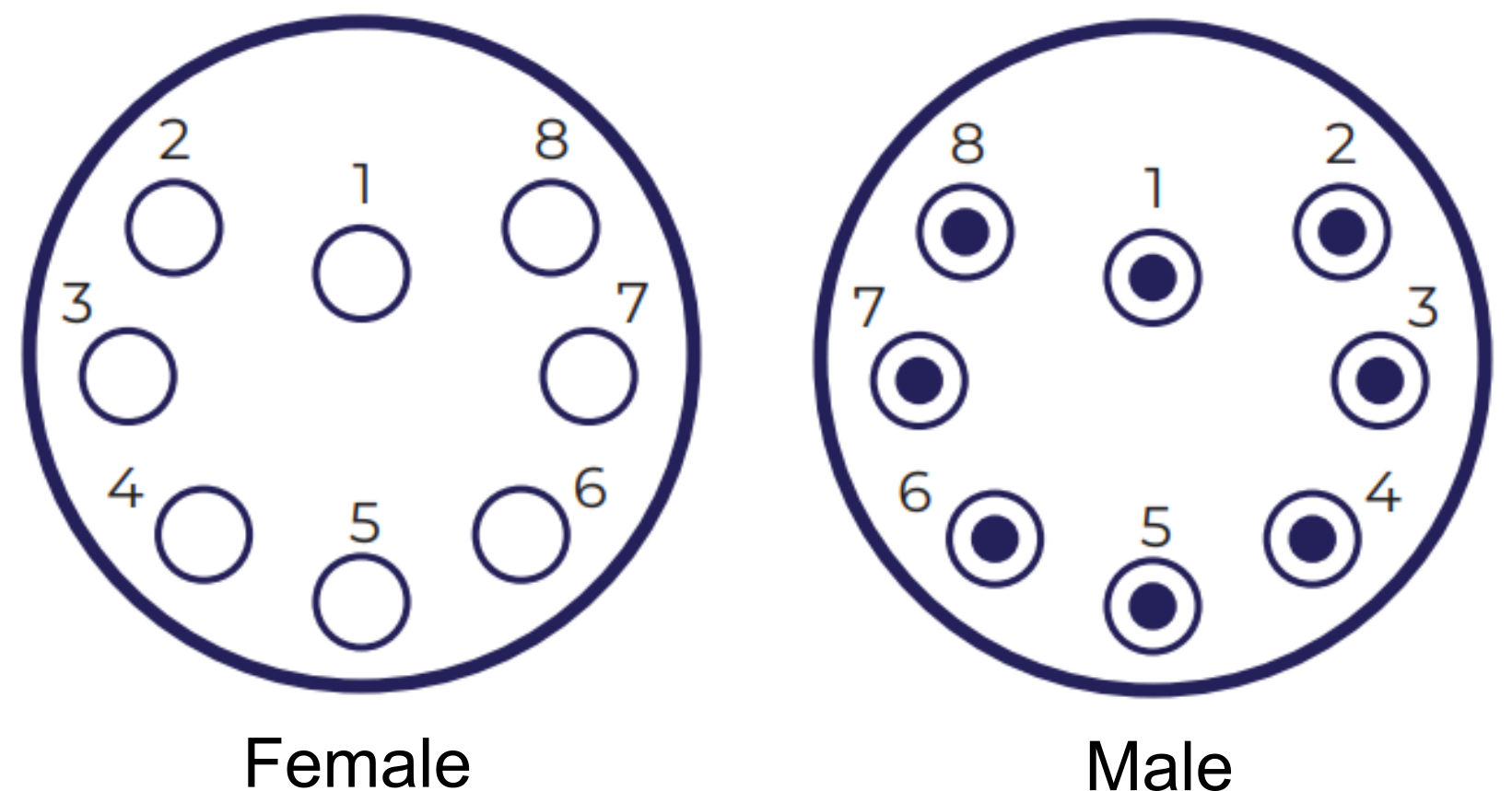
The MRU Marine S is connected to a system with the shallow water cable plugged to a SubConn connector. Because the 8-pin SubConn connector does not provide sufficient pins to accommodate power, Ethernet, RS-232, and RS-485 simultaneously, five different power and communication configurations are supported.
Marine S connector view
Overview of female and male 8-pin connectors, both supported for the MRU Marine S.
MRU Marine S signal diagram
The various MRU signal diagrams for the marine S 8-pin connector, showing pin number and associated MRU signals (including its category). Note that all signals are with respect to the MRU connector.
|
SubConn CONNECTOR CONFIGURATION 1 |
||
|---|---|---|
|
PIN NUMBER |
SIGNAL |
CATEGORY |
|
1 |
GND |
POWER |
|
2 |
24V |
|
|
3 |
GND |
|
|
4 |
24V |
|
|
5 |
Tx_D1+ |
ETHERNET |
|
6 |
Tx_D1- |
|
|
7 |
Rx_D2+ |
|
|
8 |
Rx_D2- |
|
|
SubConn CONNECTOR CONFIGURATION 2 |
||
|---|---|---|
|
PIN NUMBER |
SIGNAL |
CATEGORY |
|
1 |
GND |
POWER |
|
2 |
24V |
|
|
3 |
Tx |
RS-232 |
|
4 |
Rx |
|
|
5 |
Tx_D1+ |
ETHERNET |
|
6 |
Tx_D1- |
|
|
7 |
Rx_D2+ |
|
|
8 |
Rx_D2- |
|
|
SubConn CONNECTOR CONFIGURATION 3 |
||
|---|---|---|
|
PIN NUMBER |
SIGNAL |
CATEGORY |
|
1 |
GND |
POWER |
|
2 |
24V |
|
|
3 |
Tx |
RS-232 |
|
4 |
Rx |
|
|
5 |
Tx+ |
RS-485 |
|
6 |
Tx- |
|
|
7 |
Rx+ |
|
|
8 |
Rx- |
|
|
SubConn CONNECTOR CONFIGURATION 4 |
||
|---|---|---|
|
PIN NUMBER |
SIGNAL |
CATEGORY |
|
1 |
GND |
POWER |
|
2 |
24V |
|
|
3 |
GND |
|
|
4 |
24V |
|
|
5 |
Tx+ |
RS-485 |
|
6 |
Tx- |
|
|
7 |
Rx+ |
|
|
8 |
Rx- |
|
|
SubConn CONNECTOR CONFIGURATION 5 |
||
|---|---|---|
|
PIN NUMBER |
SIGNAL |
CATEGORY |
|
1 |
GND |
POWER |
|
2 |
24V |
|
|
3 |
(B)+ |
RS-485 |
|
4 |
(A)- |
|
|
5 |
Tx_D1+ |
ETHERNET |
|
6 |
Tx_D1- |
|
|
7 |
Rx_D2+ |
|
|
8 |
Rx_D2- |
|