Junction Box 2.0 features a plug-and-play design with simple interfacing. Junction Box 3.1, on the other hand, offers a more advanced and flexible interface, with additional support for analog outputs. This page provides an overview of the electrical interfaces of both variants.
Junction box 2.0
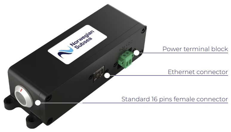
A Norwegian Subsea junction box 2.0 interfaces the MRU Marine to Ethernet, RS-232 or RS-485 ports of a system. The main connector in the front of the junction box is mated with a marine cable from the MRU. The nominal power input to the MRU Marine is 24 V DC. The MRU will work with input voltages from 10-36 V. The unit is protected against reverse polarity. If input voltage drops below 12 V, the unit will shut down safely. There is no over-voltage protection. Hence, too high input voltage may damage the MRU Marine permanently. Power consumption is approximately 6 W.
Connector overview
Junction box 2.0 consists of five connectors:
-
Power: 9–36 VDC input, terminal block.
-
Ethernet: Ethernet communication, RJ45.
-
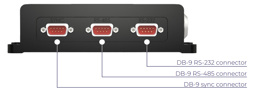
RS-485: Serial communication (RS-485), DB-9.
-
RS-232: Serial communication (RS-232), DB-9.
-
Sync: Time synchronization, DB-9.
An overview of the connectors and their associated pinout diagrams are given below.
|
POWER - BARREL JACK 2.1 mm |
|
|---|---|
|
PIN NUMBER |
SIGNAL |
|
+ |
10-36 V DC |
|
- |
GND |
|
ETHERNET, RJ45 |
|
|---|---|
|
PIN NUMBER |
SIGNAL |
|
1 |
Tx_D1+ |
|
2 |
Tx_D1- |
|
3 |
Rx_D2+ |
|
6 |
Rx_D2- |
|
RS-485, DB-9 (male) |
|
|---|---|
|
PIN NUMBER |
SIGNAL |
|
8 |
Tx+ (RS-485) |
|
9 |
Tx- (RS-485) |
|
5 |
Rx- (RS-485) |
|
4 |
Rx+ (RS-485) |
|
1 |
GND |
|
RS-232, DB-9 (male) |
|
|---|---|
|
PIN NUMBER |
SIGNAL |
|
3 |
Tx (RS-232) |
|
2 |
Tx (RS-232) |
|
5 |
GND |
|
SYNC, DB-9 (male) |
|
|---|---|
|
PIN NUMBER |
SIGNAL |
|
7 |
Sync1 (PPS) |
|
9 |
Sync2 (RX GPS) |
|
8 |
GND |
|
6 |
GND |
Junction box 3.1
The Norwegian Subsea Junction Box 3.1 provides flexible interfacing of the MRU Marine, MRU Marine S and MRU Subsea with a system via Ethernet, RS-232, and RS-485 ports, and also includes support for analog outputs (over RS-485). A pigtail connection is required on the side connected to the junction box.

Connector overview
Junction box 3.1 consists of six actively used connectors and two switches:
-
J4: Analog outputs.
-
J5: Serial ports and sync lines.
-
J6: Power and ground.
-
J7: Ethernet.
-
J8: Ethernet to MRU.
-
J9: Power, ground, serial ports to MRU.
-
Power switch: Enable/disable power to PCB.
-
Dip switch: Analog output via RS-232/RS-485.
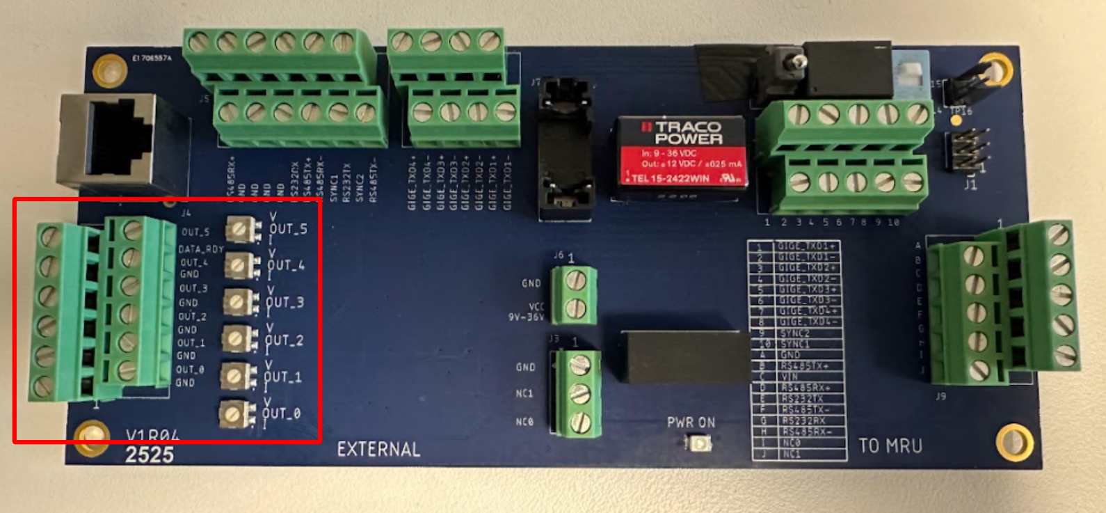
An overview of the connector pinout diagrams and their internal arrangement on the PCB can be seen below.
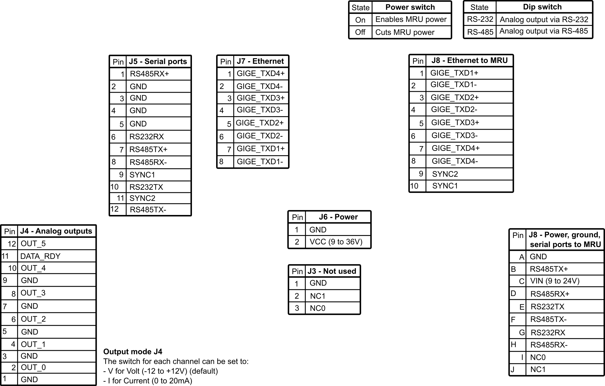
J4 - Analog outputs
There are 6 analog output channels that can be configured to output volt (-12 to 12 V) or current (0 to 20mA). Analog Outputs (J4) and switches for volt/current mode selection can be seen on the PCB in the outlined area below.
The J4 connector pinout diagram is given below.
|
J4 CONNECTOR PINOUT DIAGRAM |
||
|---|---|---|
|
PIN NUMBER |
SIGNAL |
NOTE |
|
1 |
GND |
|
|
2 |
OUT_0 |
|
|
3 |
GND |
|
|
4 |
OUT_1 |
|
|
5 |
GND |
|
|
6 |
OUT_2 |
|
|
7 |
GND |
|
|
8 |
OUT_3 |
|
|
9 |
GND |
|
|
10 |
OUT_4 |
|
|
11 |
DATA_RDY |
This signal indicates that all channels have been updated. It will go from 0V to 5V for 10 microseconds and return to 0V. |
|
12 |
OUT_5 |
|
The switch for each channel (0 to 5) can be set to V for Volt (default) and I for current output mode, respectively.
J5 - Serial ports and sync lines
On the J5 connector, there are 2 serial ports (1 × RS-232 and 1 × RS-485) along with 2 sync lines, as shown on the PCB in the outlined area below.
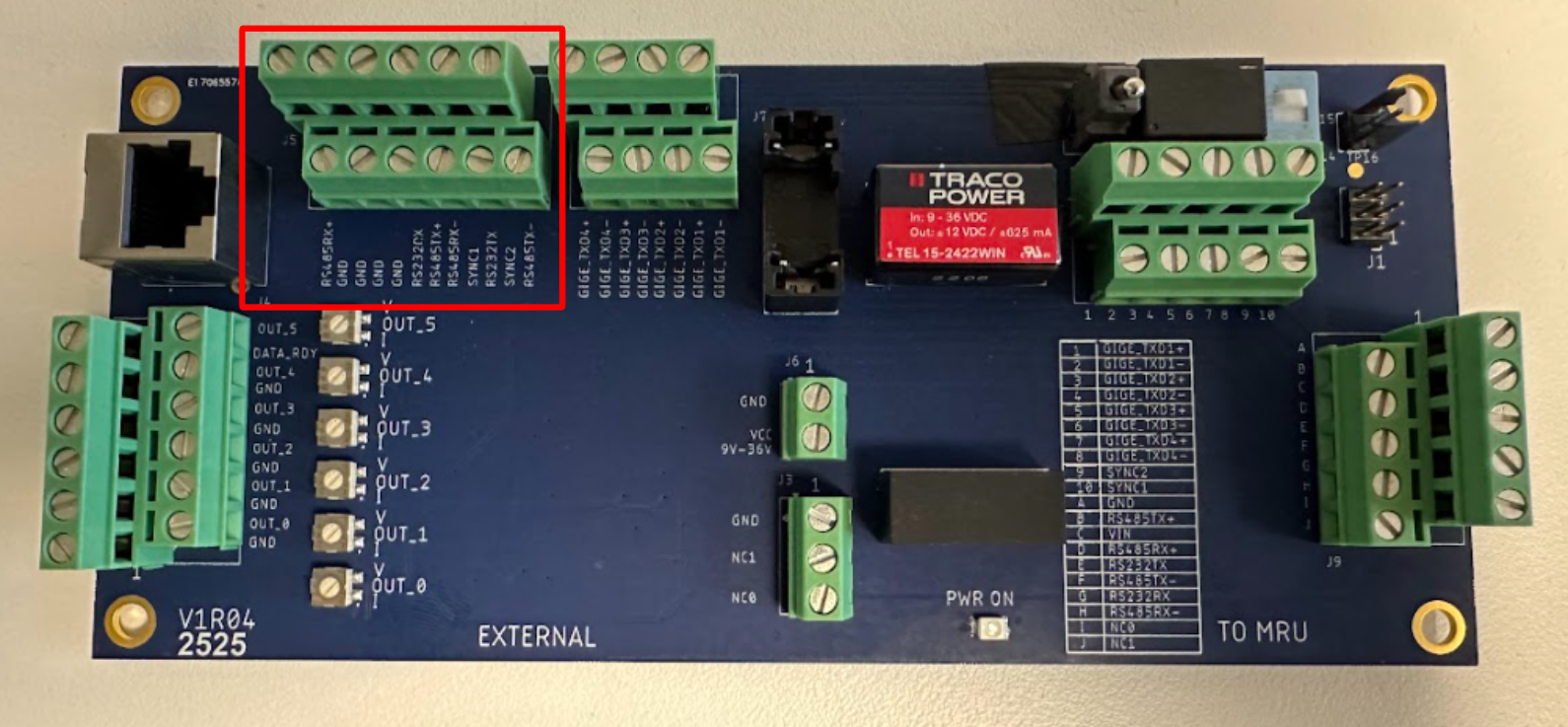
The J5 connector pinout diagram is given below.
|
J5 CONNECTOR PINOUT DIAGRAM |
|
|---|---|
|
PIN NUMBER |
SIGNAL |
|
1 |
RS485RX+ |
|
2 |
GND |
|
3 |
GND |
|
4 |
GND |
|
5 |
GND |
|
6 |
RS232RX |
|
7 |
RS485TX+ |
|
8 |
RS485RX- |
|
9 |
SYNC1 |
|
10 |
RS232TX |
|
11 |
SYNC2 |
|
12 |
RS485TX- |
J6 - Power and ground
Power and ground to the MRU are supplied via the J6 connector, which is shown on the PCB in the outlined area below.
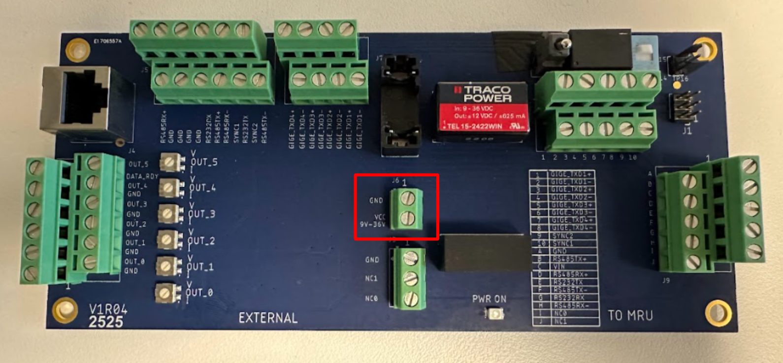
The J6 connector pinout diagram is given below.
|
J6 CONNECTOR PINOUT DIAGRAM |
|
|---|---|
|
PIN NUMBER |
SIGNAL |
|
1 |
GND |
|
2 |
VCC, input from 9V to 36V |
J7 - Ethernet
Ethernet is on the J7 connector, which is shown on the PCB in the outlined area below. The RJ45 connector on the junction box is connected to the signals GIGE_TXD2+, GIGE_TXD2-, GIGE_TXD1+ and GIGE_TXD1- on the J7 connector. This connector can be used to easily access the MRU via Ethernet.
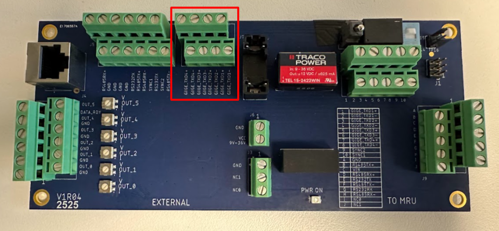
The J7 connector pinout diagram is given below.
|
J7 CONNECTOR PINOUT DIAGRAM |
|
|---|---|
|
PIN NUMBER |
SIGNAL |
|
1 |
GIGE_TXD4+ |
|
2 |
GIGE_TXD4- |
|
3 |
GIGE_TXD3+ |
|
4 |
GIGE_TXD3- |
|
5 |
GIGE_TXD2+ |
|
6 |
GIGE_TXD2- |
|
7 |
GIGE_TXD1+ |
|
8 |
GIGE_TXD1- |
J8 - Ethernet to MRU
The J8 connector is for the Ethernet signals to the MRU. It is shown on the PCB in the outlined area below.
The J8 connector pinout diagram is given below.
|
J8 CONNECTOR PINOUT DIAGRAM |
|
|---|---|
|
PIN NUMBER |
SIGNAL |
|
1 |
GIGE_TXD1+ |
|
2 |
GIGE_TXD1- |
|
3 |
GIGE_TXD2+ |
|
4 |
GIGE_TXD2- |
|
5 |
GIGE_TXD3+ |
|
6 |
GIGE_TXD3- |
|
7 |
GIGE_TXD4+ |
|
8 |
GIGE_TXD4- |
|
9 |
SYNC2 |
|
10 |
SYNC1 |
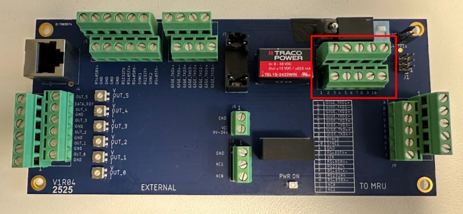
J9 - Power, Ground and Serial ports to MRU
The J9 connector is for power, ground and serial ports to the MRU, as shown on the PCB in the outlined area below.
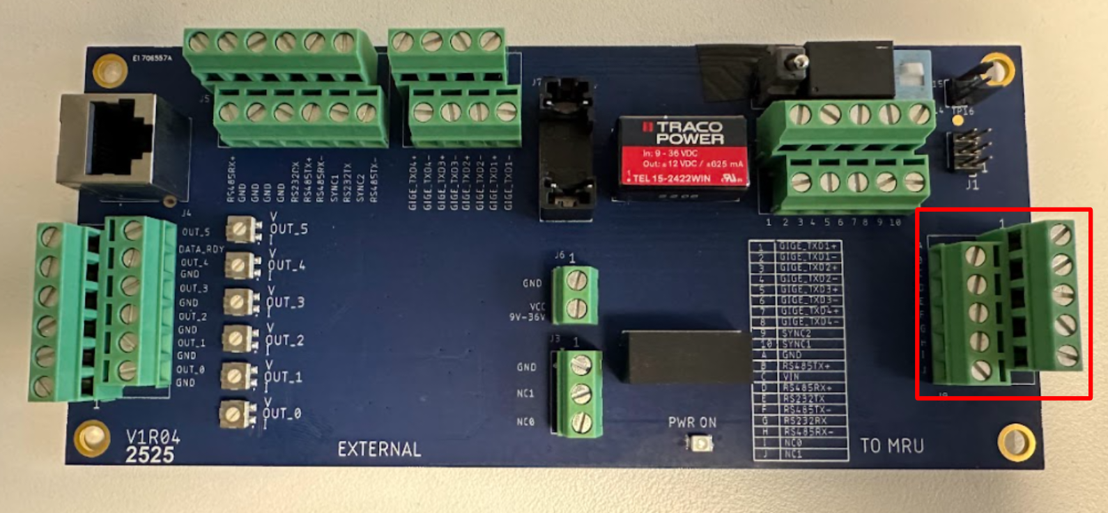
The J9 connector pinout diagram is given below.
|
J9 CONNECTOR PINOUT DIAGRAM |
|
|---|---|
|
PIN NUMBER |
SIGNAL |
|
A |
GND |
|
B |
RS485TX+ |
|
C |
V_IN (9 to 24 V) |
|
D |
RS485RX+ |
|
E |
RS232TX |
|
F |
RS485TX- |
|
G |
RS232RX |
|
H |
RS485RX- |
|
I |
NC0 |
|
J |
NC1 |
RS-485 for J9 connector
The analog junction box must be connected to the MRU via RS-485 to use the analog output channels. I.e., the RS-485 signals on the J9 connector must be connected to the MRU RS-485 port.
Power and DIP switch
The PCB includes a power switch (left red box) and a DIP switch (right red box).
-
The DIP switch selects the interface for the analog output:
-
Pushed towards the board edge → RS-232 controls the analog output.
-
Pushed towards the board center → RS-485 controls the analog output.
-
-
The power switch controls MRU power:
-
Pushed towards the board edge → MRU power disabled.
-
Pushed towards the board center → MRU power enabled.
-
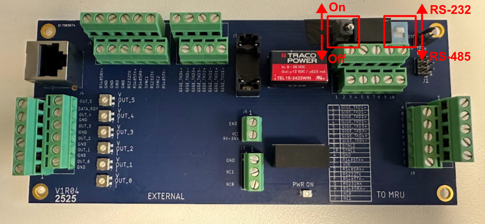
The power and DIP switch state diagrams are given below.
|
POWER SWITCH |
|
|---|---|
|
STATE |
FUNCTION |
|
On |
Enables MRU power |
|
Off |
Cuts MRU power |
|
DIP SWITCH |
|
|---|---|
|
STATE |
FUNCTION |
|
RS-232 |
Analog output via RS-232 |
|
RS-485 |
Analog output via RS-485 |