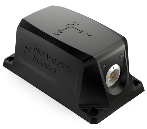
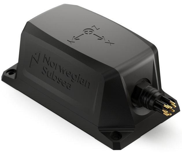
This page provides an overview of the mechanical interfaces of the MRU Marine and MRU Marine S.
MRU Marine
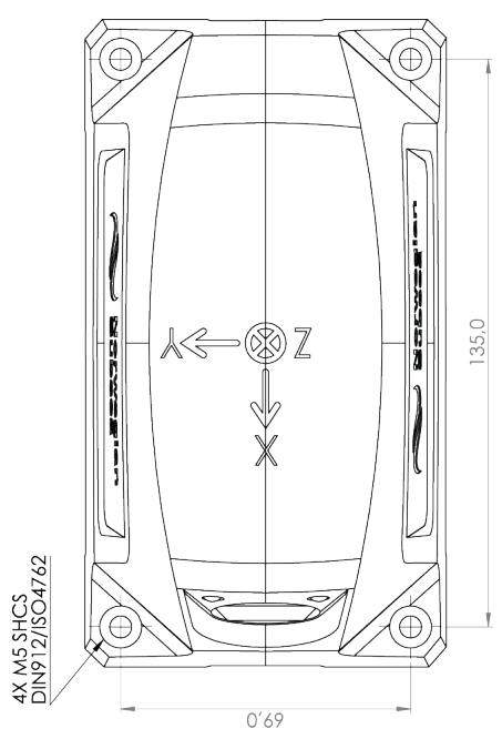
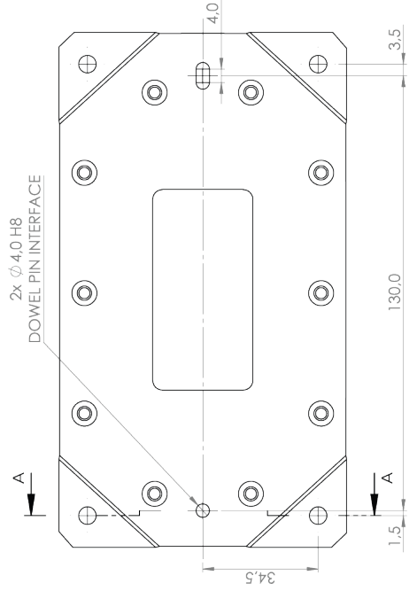
The MRU Marine have 4 mounting holes and the 2 alignment holes/slots on the center line. The MRU is mounted to a solid surface using 4 x M5 screws. 4 mm diameter alignment dowels are recommended for best alignment during installation.
Design
The dimensions of the MRU Marine are:
-
Length: 154.0 mm
-
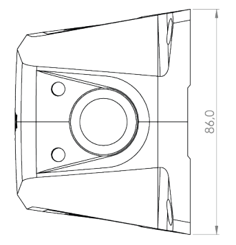
Width: 86.0 mm
-
Height: 66.6 mm
Note
The MRU Marine 3000/6000/9000 are identical when considering geometry, construction and materials.
LED indicators
The MRU Marine have two LED indicators that provide feedback on the MRU status and configuration.
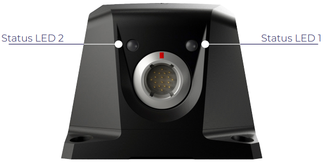
The status LED 1 provides a general overview of the MRU status. Its color indicates if the MRU is working properly, requires a restart, or if a critical error must be investigated further.
|
STATUS LED 1 |
||
|---|---|---|
|
COLOR |
BLINKING PATTERN |
DESCRIPTION |
|
Green |
Constant light |
MRU powered up, everything is OK |
|
Yellow |
Constant light |
MRU powered up, requires restart |
|
Red |
Constant light |
MRU powered up, critical error. Check status bits |
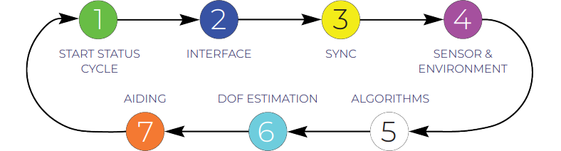
The status LED 2 provides detailed information about the MRU status from its color and blinking pattern. The status LED 2 loops through 7 colors with fixed order (see figure below), and every color is associated to a status category.
|
STATUS LED 2 |
||||
|---|---|---|---|---|
|
ORDER |
COLOR |
BLINKING PATTERN |
DESCRIPTION |
STATUS BIT |
|
1 |
Green |
1 long pulse |
Sequence start |
- |
|
2 |
Blue |
1 pulse |
Only Ethernet configuration port available |
- |
|
2 pulses |
Ethernet and RS-232 port available |
|||
|
3 pulses |
Ethernet and RS-485 port available |
|||
|
3 |
Yellow |
1 pulse |
Time and clock synced |
4, 5 |
|
2 pulses |
Time synced. Clock not synced |
|||
|
3 pulses |
Time not synced. Clock synced |
|||
|
4 pulses |
Time and clock not synced |
|||
|
4 |
Magenta |
1 pulse |
Sensor and environment OK |
9, 10, 11 |
|
2 pulses |
Sensor saturated, environment OK |
|||
|
3 pulses |
Sensor OK, temp. or vibrations out of bounds |
|||
|
5 |
White |
1 pulse |
Algorithms OK |
13, 14, 15 |
|
2 pulses |
Unstable / initializing algorithms |
|||
|
6 |
Turquoise |
1 pulse |
All DOFs OK |
16, 18, 20, 22 |
|
2 pulses |
Roll/Pitch not OK |
|||
|
3 pulses |
Heading not OK |
|||
|
4 pulses |
Heave not OK |
|||
|
5 pulses |
More than one DOF not OK |
|||
|
7 |
Orange |
1 pulse |
Position, velocity and heading aiding |
27, 28, 29 |
|
2 pulses |
Position and velocity aiding |
|||
|
3 pulses |
Position and heading aiding |
|||
|
4 pulses |
Heading and velocity aiding |
|||
|
5 pulses |
No aiding |
|||
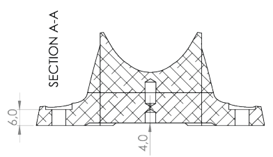
Technical drawings
MRU Marine top, side, front, bottom and section A-A technical drawings. All dimensions are in millimeters. For complete technical drawings (PDF and STEP files) of the MRU Marine, see here.
Top view
Side view
Front view
Bottom view
Section A-A
MRU Marine S
The MRU Marine S have 4 mounting holes and the 2 alignment holes/slots on the center line. The MRU is mounted to a solid surface using 4 x M5 screws. 4 mm diameter alignment dowels are recommended for best alignment during installation.
Design
The dimensions of the MRU Marine S are:
-
Length: 154.0 mm
-
Width: 86.0 mm
-
Height: 66.6 mm
Note
The MRU Marine 3000/6000/9000 S are identical when considering geometry, construction and materials.
Technical drawings
MRU Marine S top, side, front, bottom and section A-A technical drawings. All dimensions are in millimeters. For complete technical drawings (PDF and STEP files) of the MRU Marine S, see here.
Top view
Side view
Front view
Bottom view
Section A-A
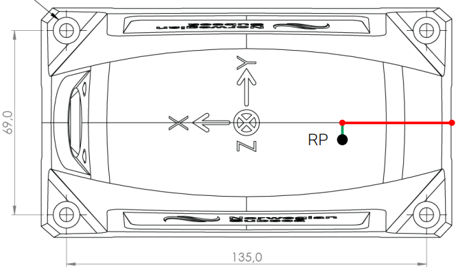
Reference point
Reference point (RP) from center aft of MRU:
-
X: 57.8 mm
-
Y: -8.9 mm
-
Z: -15.7 mm
Top view
Side view
Note
MRU Marine and MRU Marine S share the same reference point.