The electrical interface for the MRU Subsea provides a complete overview of the connectivity options available. It includes male/female connector views and descriptions of the different connector configurations.
Connector configurations
The MRU Subsea is connected to a system with the subsea cable plugged to a SubConn connector. The 8 pin SubConn connector has not enough pins for power, Ethernet, RS-232 and RS-485 ports. The 5 available power and communication configurations for the SubConn connector are given below. Note that all signals are with respect to the MRU connector.
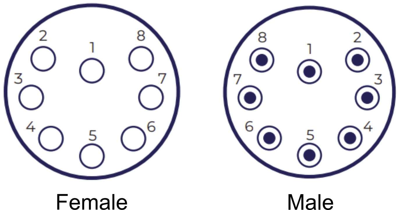
SubConn connector view
Overview of female and male 8-pin connectors, both supported for the MRU Subsea.
MRU Subsea signal diagram
MRU signal diagram for the SubConn 8-pin connector, showing pin number and associated MRU signals (including its category) for each confguration.
|
SubConn CONNECTOR CONFIGURATION 1 |
||
|---|---|---|
|
PIN NUMBER |
SIGNAL |
CATEGORY |
|
1 |
GND |
POWER |
|
2 |
24V |
|
|
3 |
GND |
|
|
4 |
24V |
|
|
5 |
Tx_D1+ |
ETHERNET |
|
6 |
Tx_D1- |
|
|
7 |
Rx_D2+ |
|
|
8 |
Rx_D2- |
|
|
SubConn CONNECTOR CONFIGURATION 2 |
||
|---|---|---|
|
PIN NUMBER |
SIGNAL |
CATEGORY |
|
1 |
GND |
POWER |
|
2 |
24V |
|
|
3 |
Tx |
RS-232 |
|
4 |
Rx |
|
|
5 |
Tx_D1+ |
ETHERNET |
|
6 |
Tx_D1- |
|
|
7 |
Rx_D2+ |
|
|
8 |
Rx_D2- |
|
|
SubConn CONNECTOR CONFIGURATION 3 |
||
|---|---|---|
|
PIN NUMBER |
SIGNAL |
CATEGORY |
|
1 |
GND |
POWER |
|
2 |
24V |
|
|
3 |
Tx |
RS-232 |
|
4 |
Rx |
|
|
5 |
Tx+ |
RS-485 |
|
6 |
Tx- |
|
|
7 |
Rx+ |
|
|
8 |
Rx- |
|
|
SubConn CONNECTOR CONFIGURATION 4 |
||
|---|---|---|
|
PIN NUMBER |
SIGNAL |
CATEGORY |
|
1 |
GND |
POWER |
|
2 |
24V |
|
|
3 |
GND |
|
|
4 |
24V |
|
|
5 |
Tx+ |
RS-485 |
|
6 |
Tx- |
|
|
7 |
Rx+ |
|
|
8 |
Rx- |
|
|
SubConn CONNECTOR CONFIGURATION 5 |
||
|---|---|---|
|
PIN NUMBER |
SIGNAL |
CATEGORY |
|
1 |
GND |
POWER |
|
2 |
24V |
|
|
3 |
(B)+ |
RS-485 |
|
4 |
(A)- |
|
|
5 |
Tx_D1+ |
ETHERNET |
|
6 |
Tx_D1- |
|
|
7 |
Rx_D2+ |
|
|
8 |
Rx_D2- |
|