Subsea cables are available in two versions - normal (terminated with connectors at both ends) and pigtail (connector on one end only) - and can be supplied in various lengths.
Normal
Cable assembly overview
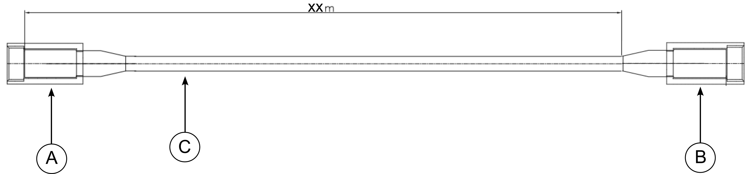
For subsea normal cables with connectors at both ends, the assembly consists of three parts:
-
Connector A: SubConn straight plug, 8-pin. Female (MCIL8F) or male (MCIL8M). Connects to the MRU.
-
Connector B: SubConn straight plug, 8-pin. Female (MCIL8F) or male (MCIL8M). Connects to the system output.
-
Cable (C): 4 × twisted pairs, length = 2-50m. For more information about the cable, see here .
Supported cable lengths and associated product numbers for subsea normal cables are given below. For complete cable product list, see here .
|
SUBSEA NORMAL CABLE PRODUCT LIST |
|
|---|---|
|
LENGTH [m] |
PRODUCT NUMBER |
|
2 |
30121 |
|
5 |
30122 |
|
10 |
30123 |
|
20 |
30124 |
|
50 |
30125 |
SubConn connector view
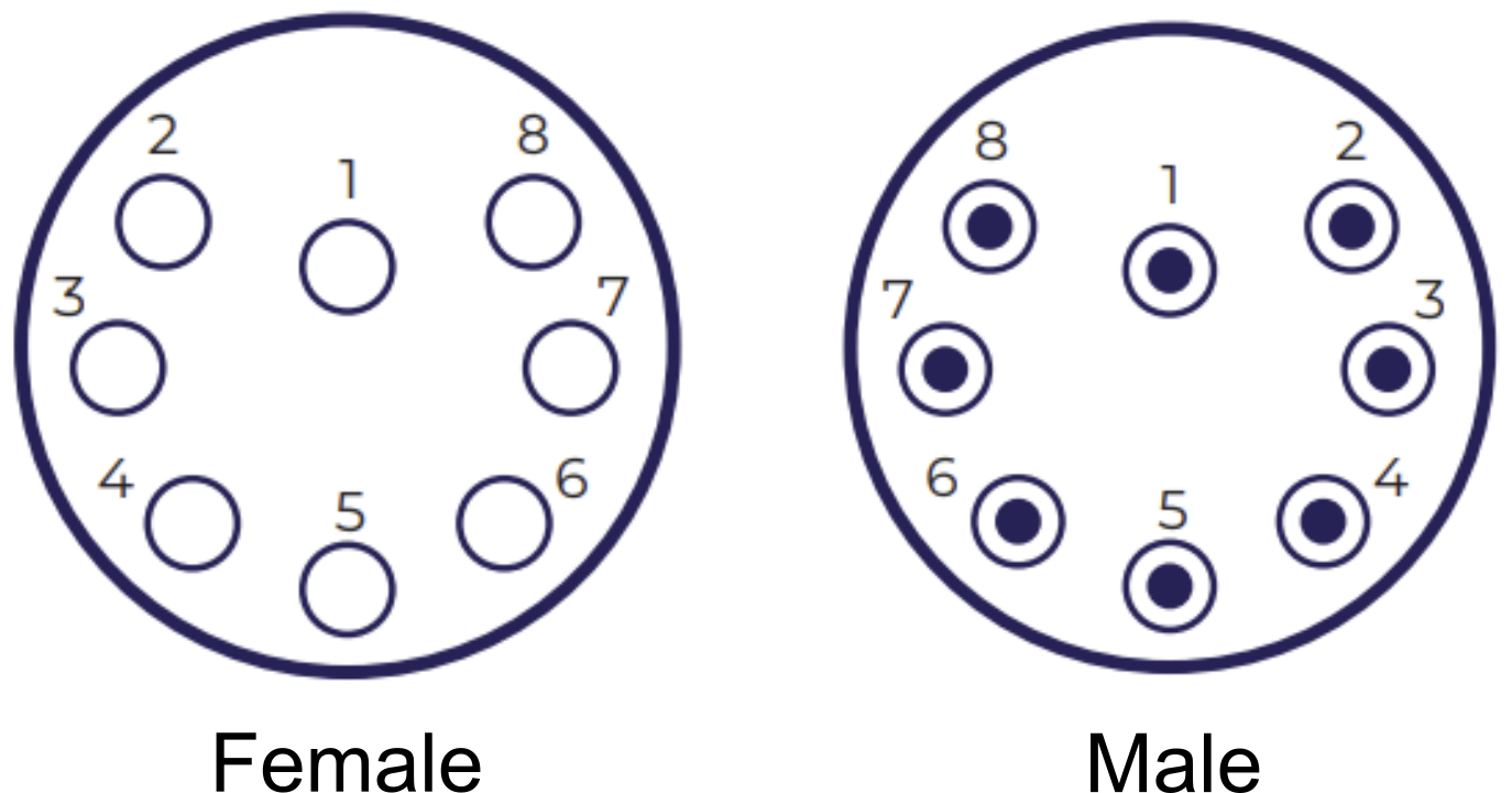
Overview of female and male connectors, both supported for the subsea normal cable.

Pinout diagram
Pinout diagram specifying the cable assembly from connector A to connector B, including pin number, wire color, and gauge/pair connections.
|
SUBSEA NORMAL CABLE ASSEMBLY PINOUT DIAGRAM |
|||
|---|---|---|---|
|
PIN (connector A) |
COLOR |
PAIR |
PIN (connector B) |
|
1 |
Black |
Pair 1 & shield |
1 |
|
2 |
White |
Pair 1 |
2 |
|
3 |
Red |
Pair 2 |
3 |
|
4 |
Green |
Pair 2 |
4 |
|
5 |
Orange |
Pair 3 |
5 |
|
6 |
Blue |
Pair 3 |
6 |
|
7 |
White/black |
Pair 4 |
7 |
|
8 |
Red/black |
Pair 4 |
8 |
Pigtail
Cable assembly overview
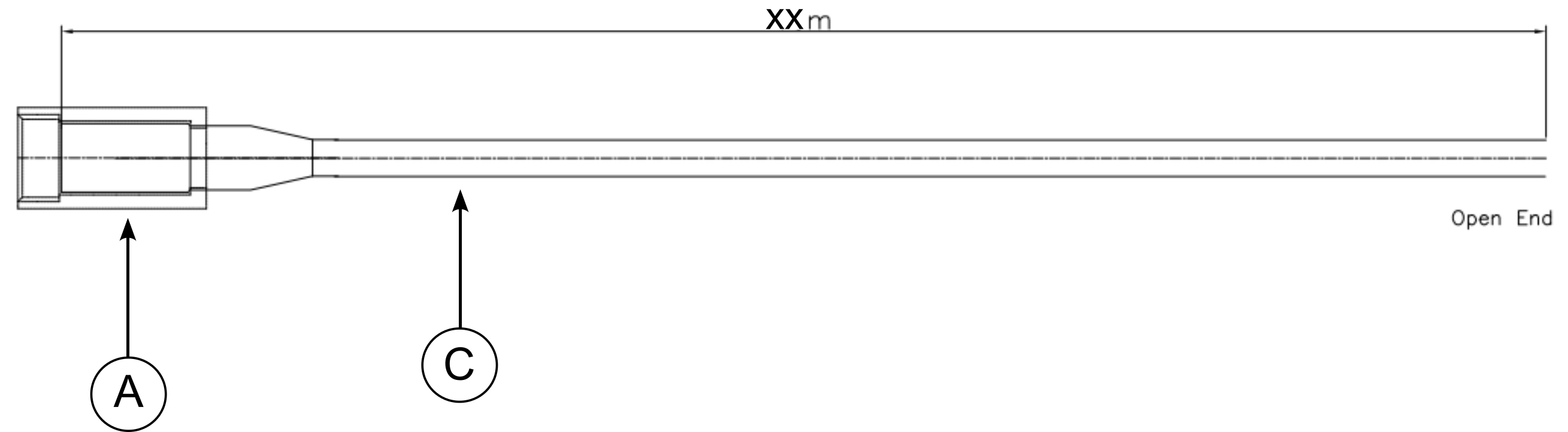
For subsea pigtail cables with connectors on one end only, the assembly consists of two parts:
-
Connector A: SubConn straight plug, 8-pin. Female (MCIL8F) or male (MCIL8M). Connects to the MRU.
-
Cable (C): For more information about the cable, see here .
Supported cable lengths and associated product numbers for subsea normal cables are given below. For complete cable product list, see here .
|
SUBSEA PIGTAIL CABLE PRODUCT LIST |
|
|---|---|
|
LENGTH [m] |
PRODUCT NUMBER |
|
2 |
30126 |
|
5 |
30127 |
|
10 |
30128 |
|
20 |
30129 |
|
50 |
30130 |
SubConn connector view
Overview of female and male connectors, both supported for the subsea pigtail cable.
Pinout diagram
Pinout diagram specifying the pigtail cable assembly, including pin number, wire color, and gauge/pair connections.
|
SUBSEA PIGTAIL CABLE ASSEMBLY PINOUT DIAGRAM |
||
|---|---|---|
|
PIN (connector A) |
COLOR |
PAIR |
|
1 |
Black |
Pair 1 & shield |
|
2 |
White |
Pair 1 |
|
3 |
Red |
Pair 2 |
|
4 |
Green |
Pair 2 |
|
5 |
Orange |
Pair 3 |
|
6 |
Blue |
Pair 3 |
|
7 |
White/black |
Pair 4 |
|
8 |
Red/black |
Pair 4 |
MRU signal diagram
To find the associated MRU signal diagram, check out section “MRU Subsea signal diagram” here .
Junction box signal diagram
To find the associated junction box diagram compatible with subsea normal and pigtail cables, check out the signal diagrams for junction box 2.0/3.0 here .
Connector compatibility
Both connector A and connector B can be either male or female, and they share the same internal pinout arrangement. Hence, they are mutually compatible. This applies to both normal and pigtail cable assemblies.